Eureka AIR delivers breakthrough ideas for toughest innovation challenges, trusted by R&D personnel around the world.

Electron mirror clean keeping infection preventing equipment for medical detection and application method of electron mirror clean keeping infection preventing equipment

An anti-infection, electronic mirror technology, applied in the direction of cleaning methods using liquids, cleaning methods and utensils, chemical instruments and methods, etc., can solve cross-infection and increase the risk of infectious diseases, electronic mirrors are easy to hide dirt, cleaning machinery Insufficient strength and other problems, to achieve the effect of increasing the ultrasonic cleaning function, realizing cleaning, disinfection and sterilization, and quick and convenient cleaning

Inactive Publication Date: 2018-03-30
陈明光
View PDF8 Cites 0 Cited by
  • Summary
  • Abstract
  • Description
  • Claims
  • Application Information

AI Technical Summary

Problems solved by technology

Due to its small size, the object in the cavity to be observed is converted into image information through the tiny objective optical system, and then the received image signal is sent to the image processing system through the image guide fiber bundle, and finally the processed image is output on the monitor. The images are for doctors to observe and diagnose. The application of electronic mirrors is of great significance to the physical examination of the lungs, stomach, intestines, larynx, bronchus, etc. in the human body and the prevention and discovery of organ lesions. The electronic mirror has been polluted by human body fluids and bacteria and viruses in the lesion. The polluted electronic mirror has undoubtedly become a source of infection for viruses, bacteria and infectious diseases. In this case, the electronic mirror brings convenience to medical testing and diagnosis. Inevitably cause direct infection or pollution to objects and different human bodies in contact with the electronic mirror. Because the structure of the electronic mirror is easy to hide dirt, and the electronic mirror is relatively expensive and its probe is fragile, it cannot be cleaned with a strong mechanical method. Disinfection. Most of the current methods of disinfecting electronic mirrors are repeatedly cleaned and soaked by cleaning and disinfection devices. However, the problems of the current cleaning methods are that the cleaning is not thorough, the mechanical strength of the cleaning is not enough, and the electronic mirror is limited by its fragility and damage. Long cleaning time and high labor intensity
In addition, since the cleaning tank of the existing cleaning equipment cannot be replaced, after repeated contact between the cleaning tank and the polluted electronic mirror, the tank body has also become a source of infection of diseases, and cleaning the electronic mirror with the tank body has Cross-infection increases the risk of infectious disease

Method used


Image

  • Electron mirror clean keeping infection preventing equipment for medical detection and application method of electron mirror clean keeping infection preventing equipment
  • Electron mirror clean keeping infection preventing equipment for medical detection and application method of electron mirror clean keeping infection preventing equipment
  • Electron mirror clean keeping infection preventing equipment for medical detection and application method of electron mirror clean keeping infection preventing equipment

Examples


Embodiment 1

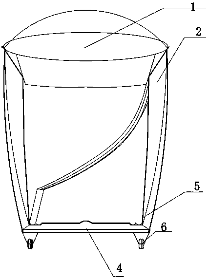
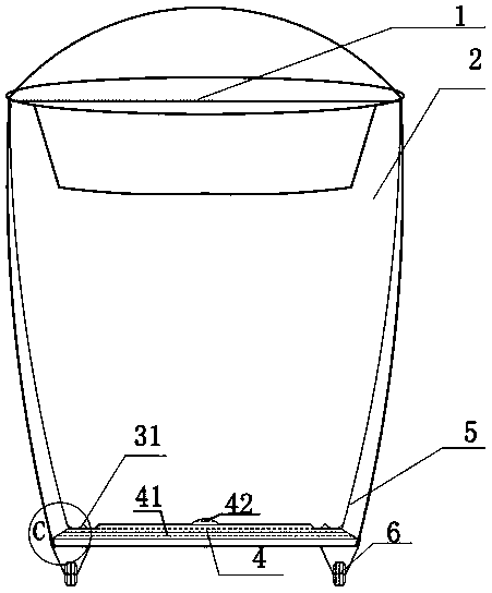
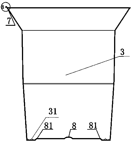
[0030] Please refer to Figures 1 to 7, an electronic mirror cleaning and anti-infection equipment for medical inspection, at least including an equipment body 2, an anti-infection cylinder 3, and a sterilizing device 4, the sterilizing device is at the bottom of the equipment body 2, the An anti-infection cylinder 3 is arranged in the equipment body, and the anti-infection cylinder 3 is assembled in the inner space of the anti-infection equipment body, and the anti-infection cylinder 3 is arranged on the bottom end surface of the sterilizing device 4, as Figure 1 to Figure 4 As shown, the shape of the contact surface between the upper end surface of the sterilizing device 4 and the bottom of the anti-infection cylinder 3 is a bump of any geometric shape, and the bottom surface of the anti-infection cylinder 3 and the upper end surface of the sterilizing device 4 The contact part is a groove of corresponding shape, and the outer end surface of the base of the anti-infection cyl...

Embodiment 2

[0035] See Figures 1 to 7 , on the basis of embodiment 1, the body structure of the electronic mirror cleaning and anti-infection equipment for medical inspection, sterilizing device and anti-infection cylinder are described in detail below,

[0036] The anti-infection device also includes an anti-infection device wall. In this embodiment, an anti-infection device wall is preferably made of iron, a bottom, preferably a flat bottom made of ferromagnetic metal, and a connector. The anti-infection device wall is not directly connected to the bottom. It is connected to the bottom through the connecting piece, specifically with reference to Fig. 2 and Fig. 7, and the details are as follows: a bottom structure of an anti-infection device, including a metal anti-infection device wall 11, a flat bottom made of ferromagnetic metal 12. Plastic fixing block 13. The anti-infection device wall 11 is not directly connected to the bottom 12, but is connected to the bottom 12 through a fixi...

Embodiment 3

[0039] On the basis of Embodiment 1 and Embodiment 2, the structure below the trapezoidal vertical section of the electronic mirror cleaning and anti-infection equipment for medical inspection will be described in detail below. The anti-infection cylinder has a bottom, an outer surface and an inner surface , the bottom and the inner surface enclose an accommodating space, the outer surface is in the shape of a transitional curved surface, the inner surface has a plurality of protruding lines extending longitudinally, and these protruding lines are arranged around the inner surface, between each two protruding lines A longitudinally extending inner concave portion is formed; wherein, the inner surface radially protrudes at least one thickened rib wall, and the thickened rib wall separates at least a part of the protruding line and at least a part of the inner concave part into interval corrugated areas, which increases The role of ultrasonic cleaning function, combined with the ...


PUM

PropertyMeasurementUnit
thicknessaaaaaaaaaa

Abstract

The invention relates to a cleaning and clean keeping device for a human body electron detection mirror and an application method. The cleaning and clean keeping device specifically at least comprisesan equipment body, an infection preventing cylinder and a sterilization device. The infection preventing cylinder is specially used by special people. The sterilization device is arranged at the bottom of the equipment body. The infection preventing cylinder is assembled in the space in the infection preventing equipment body. The infection preventing cylinder is arranged on the bottom end face of the sterilization device. The shape of the part of the contact face of the upper end face of the sterilization device and the bottom of the infection preventing cylinder is a protruding block in anygeometrical shape. The contact part of the bottom of the infection preventing cylinder and the upper end face of the sterilization device is a groove with a corresponding shape. The outer end face ofthe base of the infection preventing cylinder and the upper end face of the bottom end face of the sterilization device are arranged in a convex-concave sleeving manner so that the infection preventing cylinder specially used by special people can be conveniently sleeved and replaced. According to the cleaning and clean keeping device for the human body electron detection mirror and the application method, the problem of repeated multi-time contact with a contaminated electron mirror and cross infection does not exist, and the cleaning and clean keeping device is high in practicability and has wide purposes particularly in the fields of medical treatment, hospitals and the like.

Description

technical field [0001] The invention relates to the field of medical equipment, in particular to a cleaning device and a use method of an electronic inspection mirror for human body. Background technique [0002] The electronic detection mirror is a medical electronic optical instrument that can be inserted into the human body cavity and the inner cavity of organs for direct observation, diagnosis, and treatment. It integrates high-tech technologies such as light, mechanics, and electricity. Due to its small size, the object in the cavity to be observed is converted into image information through the tiny objective optical system, and then the received image signal is sent to the image processing system through the image guide fiber bundle, and finally the processed image is output on the monitor. The images are for doctors to observe and diagnose. The application of electronic mirrors is of great significance to the physical examination of the lungs, stomach, intestines, la...

Claims


Application Information

Patent Timeline
Patent Type & Authority Applications(China)
IPC IPC(8): B08B3/12A61L2/10A61L2/18
CPCA61L2/10A61L2/18A61L2202/17A61L2202/24B08B3/12
Inventor 陈明光刘长青葛福珍高成旭张良
Owner 陈明光
Why Eureka
Eureka Blog
Learn More