Carding machine with coiler

A technology of coiler and carding machine, applied in winding mechanism, coiling mechanism, deburring device, etc., can solve the problems of wire loss, broken ends, removal of short lint, unclean dust and so on

Inactive Publication Date: 2018-03-30
袁文林
View PDF0 Cites 0 Cited by
  • Summary
  • Abstract
  • Description
  • Claims
  • Application Information

AI Technical Summary

Problems solved by technology

[0002] In the production process of the carding machine in the prior art, there is a lot of cotton linters and dust accumulation at the bell mouth of the coiler, which will adhere to the cotton sliver intermittently, causing yarn defects in the downstream, affecting the quality of the yarn, resulting in drawing, Broken ends of roving and spun yarns, increased shear number of winding machine, resulting in loss of returned wire
[0003] At present, the Chinese patent with the application number 201290326774.9 on the market discloses a device for the accumulation of linters and dust at the bell mouth of the carding machine coiler, including a coiler, and a guide wheel is installed directly above the coiler through a bracket. There are 3 elliptical rotating blades evenly distributed on the upper ring of the guide wheel. When the guide wheel on the coiler runs with the sliver, the rotating blades are driven to rotate at the same time. The rotating rotating blades form a small fan, although it can Clean up the lint and dust generated during production, but the lint and dust will fly into the air, and the removal of lint and dust will still happen, so there is a certain room for improvement

Method used


Image

  • Carding machine with coiler
  • Carding machine with coiler
  • Carding machine with coiler

Examples


Embodiment Construction

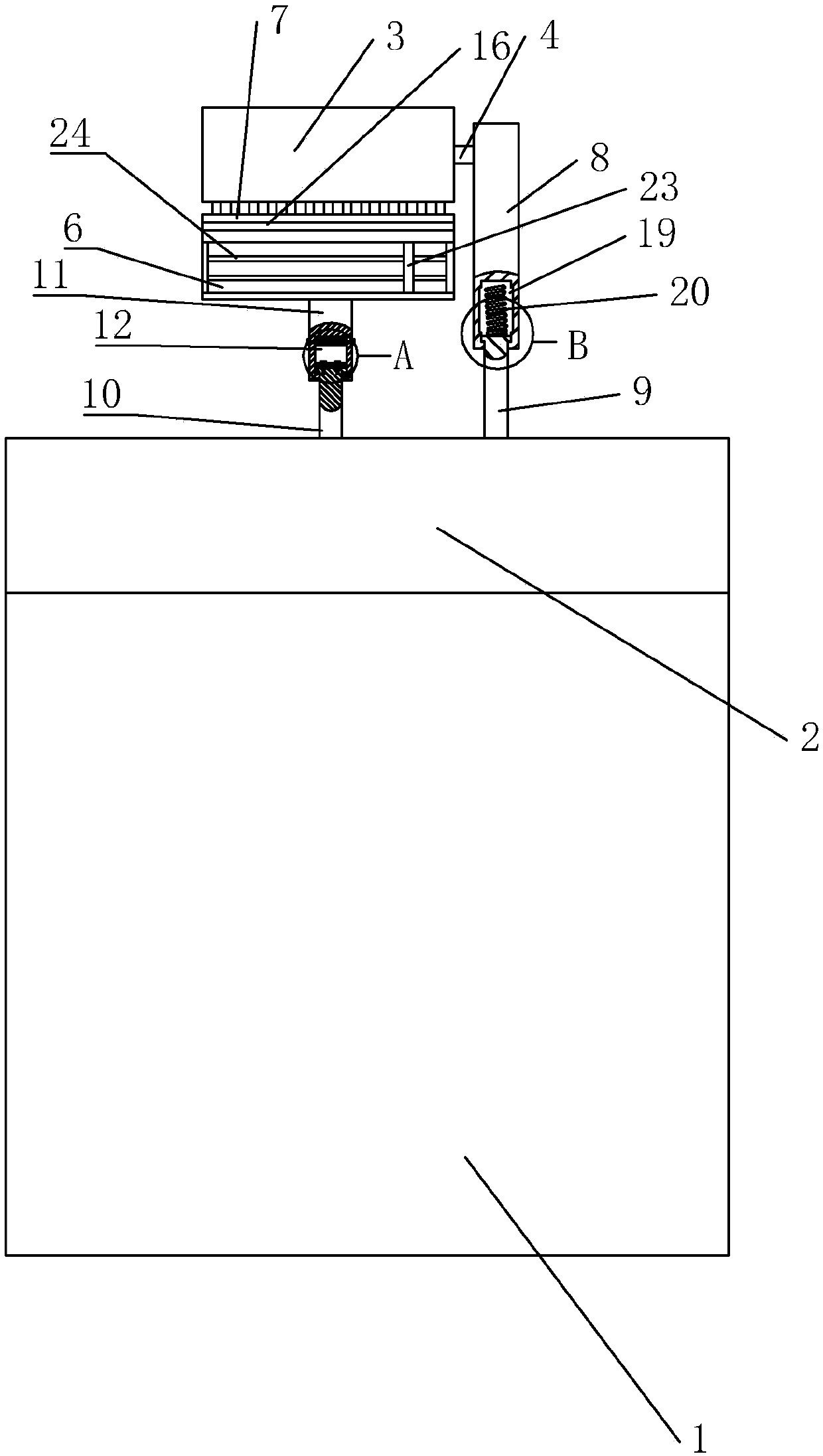
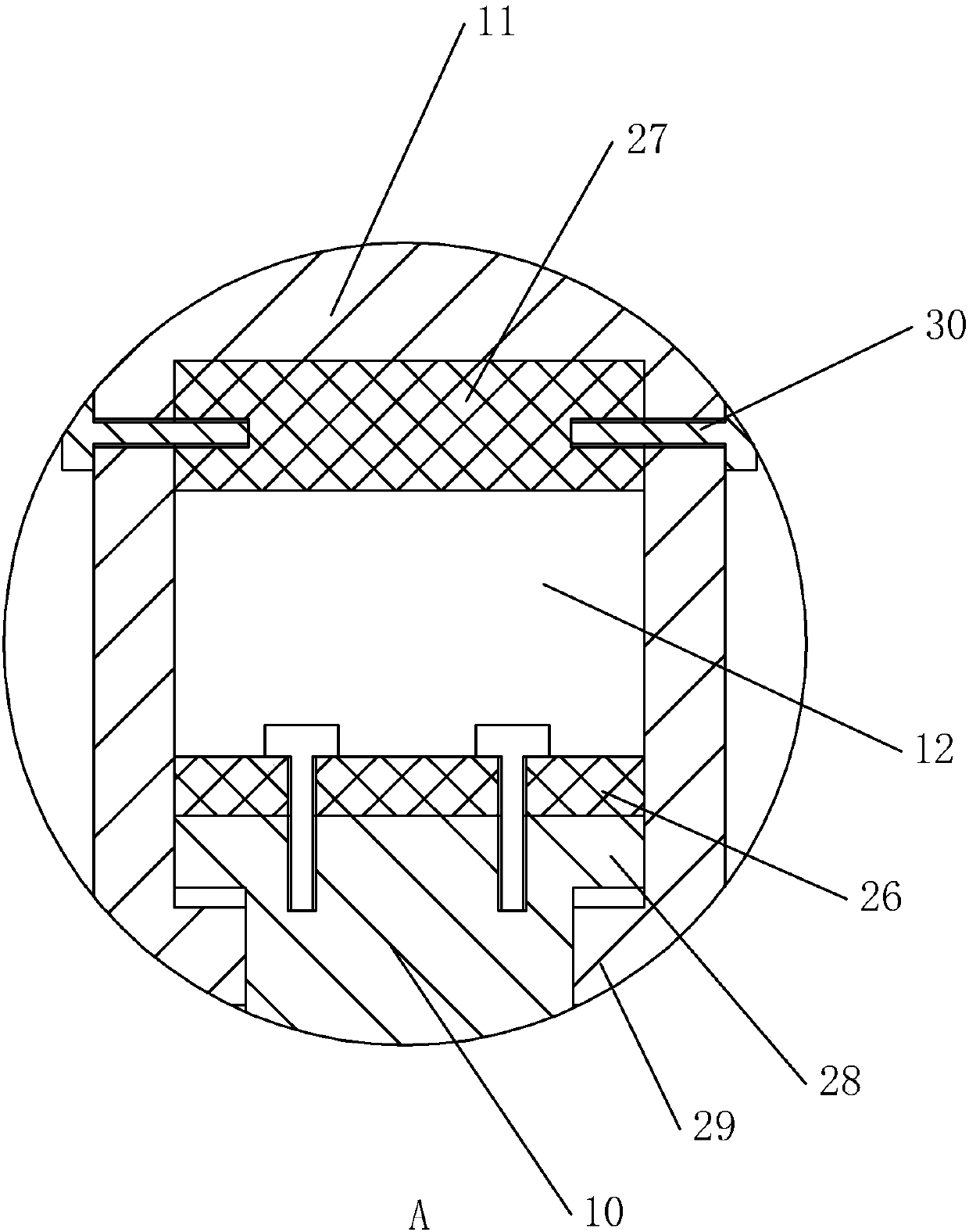
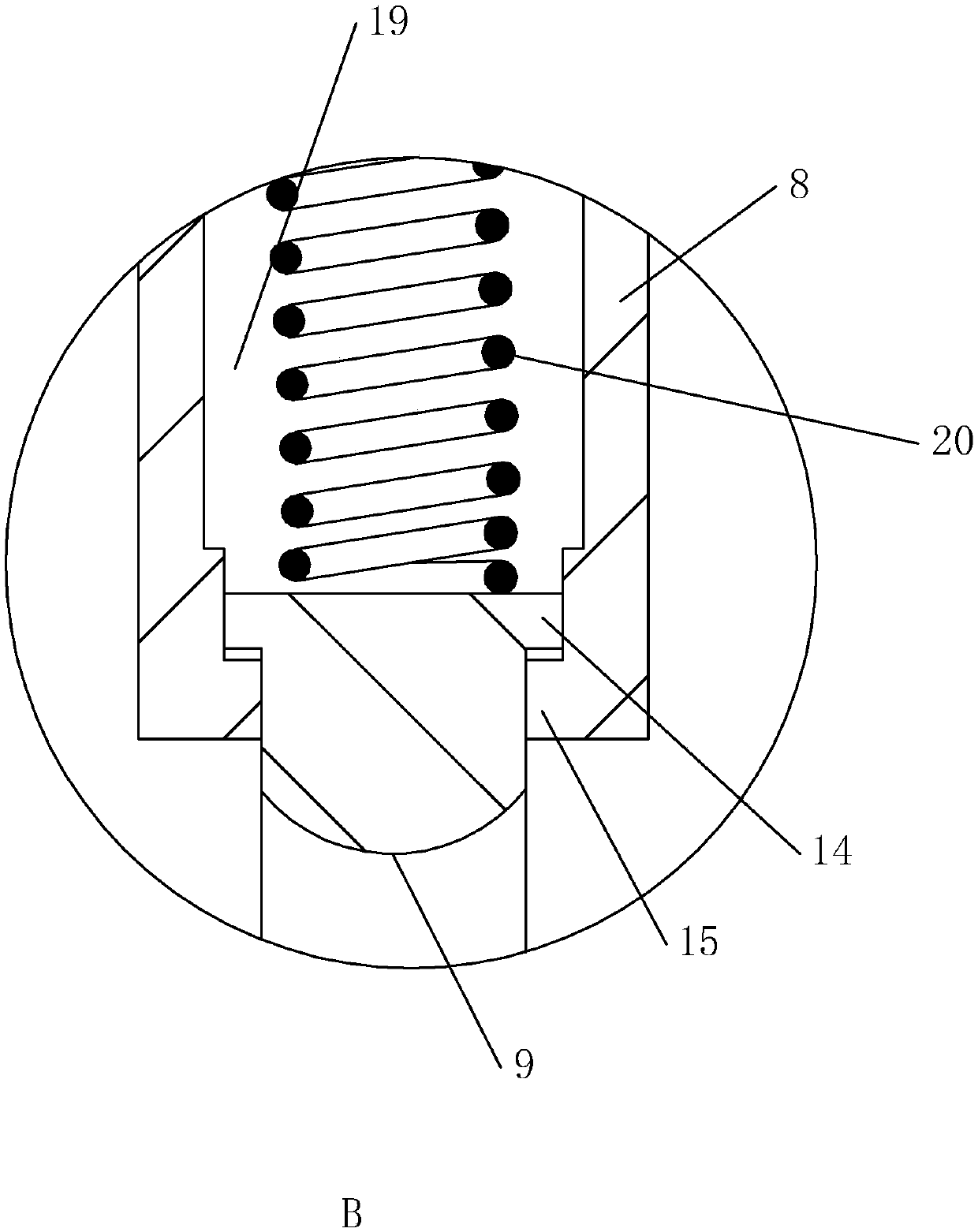
[0028] refer to Figure 1 to Figure 3 As shown, a carding machine with a coiler implemented in this case includes a coiler, and the coiler includes a barrel body 1 and a halter cover 2 installed on the barrel body 1, and the halter cover Shell 2 is provided with support frame and cylinder 3, and described cylinder 3 is installed on the halter cover shell 2 by support frame, and described support frame is set as first support frame 8 and second support frame 9, and described cylinder 3 and second The support frame 9 is connected, one end of the first support frame 8 is connected with the halter cover 2, and the other end is connected with the second support frame 9, and the first support frame 8 is provided with a mounting groove for placing the second support frame 9 19. An elastic member 20 is installed in the installation groove 19, and the two ends of the elastic member are respectively connected with the first support frame 8 and the second support frame 9, and the bottom ...


PUM


Abstract

The invention discloses a carding machine with a sliver coiler, the technical points of which include the coiler, the sliver coiler includes a halter cover, a support frame and a drum are arranged on the halter cover, and the drum is installed through the support frame On the bridle cover, the support frame is set as the first support frame and the second support frame, and the first support frame is provided with a mounting groove, and an elastic member is installed in the mounting groove, and the two ends of the elastic member are connected with the first support frame and the second support frame respectively. The two support frames are connected, a scraper is provided under the drum, and a fixed frame is provided between the scraper and the bridle cover. Rod placement slot, the first fixed rod is provided with the first magnet, and the second fixed rod is provided with the second magnet, the first magnet and the second magnet are fixed by bolts, which can timely remove the lint and dust generated during production Clean, the technical effect that can effectively guarantee the quality of cotton thread, improve production efficiency and product benefit.

Description

technical field [0001] The invention belongs to the field of textile machinery, more specifically, it relates to a carding machine with a coiler. Background technique [0002] In the production process of the carding machine in the prior art, there is a lot of cotton linters and dust accumulation at the bell mouth of the coiler, which will adhere to the cotton sliver intermittently, causing yarn defects in the downstream, affecting the quality of the yarn, resulting in drawing, The roving and spun yarns break, and the shear number of the winding machine increases, resulting in the loss of returned silk. [0003] At present, the Chinese patent with the application number 201290326774.9 on the market discloses a device for the accumulation of linters and dust at the bell mouth of the carding machine coiler, including a coiler, and a guide wheel is installed directly above the coiler through a bracket. There are 3 elliptical rotating blades evenly distributed on the upper ring...

Claims


Application Information

Patent Timeline
Patent Type & Authority Applications(China)
IPC IPC(8): D01G15/02D01G15/82D01G25/00D01G27/00
CPCD01G15/02D01G15/82D01G25/00D01G27/00
Inventor 袁文林
Owner 袁文林
Why Eureka
Try Eureka