Passenger car gasoline engine turbocharger bearing body
A technology of turbocharger and bearing body, applied in the direction of bearings, bearing cooling, bearing components, etc., can solve the problems of uneven cooling and poor cooling effect, and achieve the effect of obvious cooling effect, small space occupation, and rapid cooling effect.
- Summary
- Abstract
- Description
- Claims
- Application Information
AI Technical Summary
Problems solved by technology
Method used
Image

Examples
Embodiment Construction
[0014] The following will clearly and completely describe the technical solutions in the embodiments of the present invention with reference to the accompanying drawings in the embodiments of the present invention. Obviously, the described embodiments are only some, not all, embodiments of the present invention. Based on the embodiments of the present invention, all other embodiments obtained by persons of ordinary skill in the art without making creative efforts belong to the protection scope of the present invention.
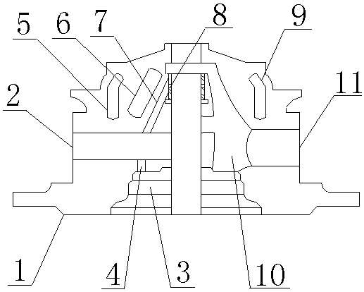
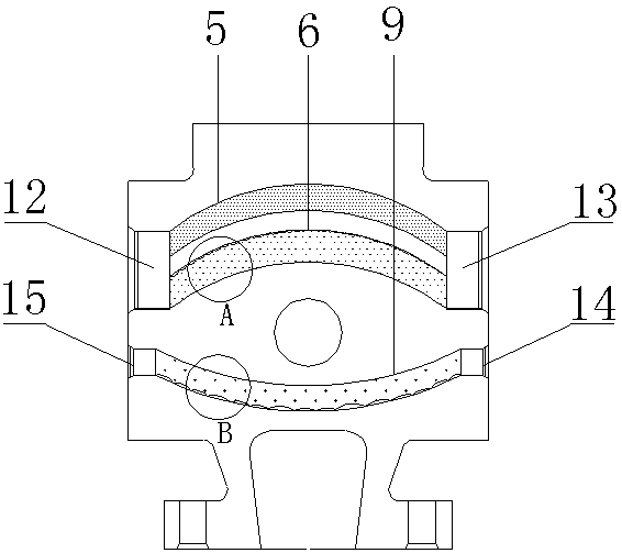
[0015] see Figure 1-2 , the present invention provides a technical solution: a passenger car gasoline engine turbocharger bearing body, including a bearing body 1, a thrust bearing oil inlet 4, a first annular cooling water chamber 5, a floating bearing oil inlet 7, a third annular Cooling water cavity 9, first cooling water inlet 12 and first cooling water outlet 13, bearing body oil inlet 2 is arranged above bearing body 1, and bearing body 1 includes thrus...
PUM
 Abstract
Description
Claims
Application Information
 - Generate Ideas
- Intellectual Property
- Life Sciences
- Materials
- Tech Scout
- Unparalleled Data Quality
- Higher Quality Content
- 60% Fewer Hallucinations
Browse by: Latest US Patents, China's latest patents, Technical Efficacy Thesaurus, Application Domain, Technology Topic, Popular Technical Reports.
© 2025 PatSnap. All rights reserved.Legal|Privacy policy|Modern Slavery Act Transparency Statement|Sitemap|About US| Contact US: help@patsnap.com