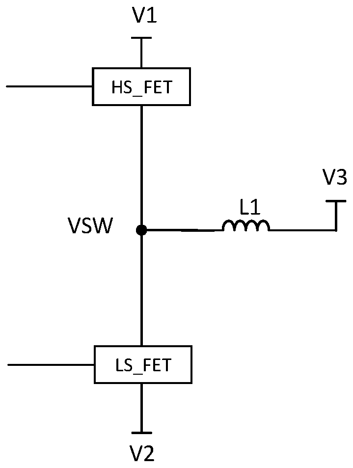
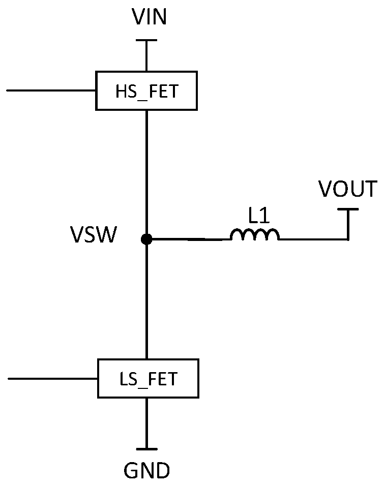
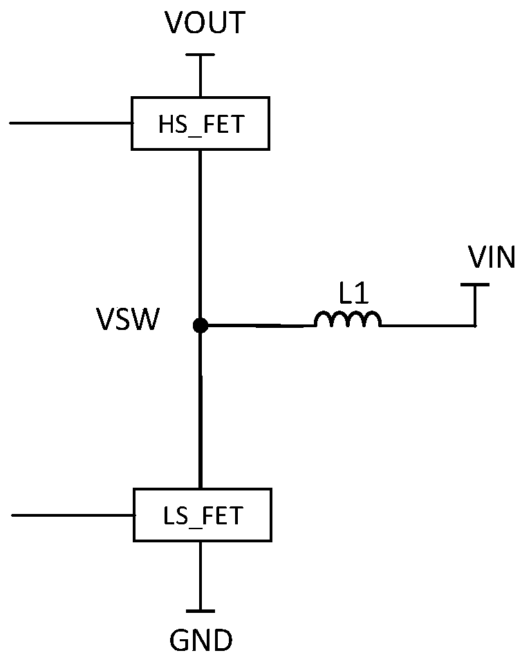
A switching power supply drive circuit based on pwm control
A technology for driving circuits and timing control circuits, which is applied in the direction of high-efficiency power electronic conversion, electrical components, and output power conversion devices, etc., can solve problems such as large reverse recovery loss, and achieve the effect of reducing reverse recovery loss.
- Summary
- Abstract
- Description
- Claims
- Application Information
AI Technical Summary
Problems solved by technology
Method used
Image
Examples
Embodiment 2
[0084] combine Figure 10 , to describe Embodiment 2 of the present invention in detail, but does not limit the claims of the present invention in any way.
[0085] in such as Figure 6 In the basic construction unit of the switching power supply circuit shown, when the inductor current flowing out of the VSW node is negative, the body diode of the HS_FET will conduct and bring a relatively large The reverse recovery loss, so HS_FET needs a new drive circuit to reduce the reverse recovery loss caused by the HS_FET body diode.
[0086] Such as Figure 10 As shown, a switching power supply drive circuit based on PWM control. The switching power supply circuit at least includes an upper MOS transistor HS_FET, a lower MOS transistor HS_FET and an inductor L1. The gate of HS_FET is used to access the driving signal of HS_FET, and the gate of LS_FET is used for When the LS_FET drive signal is connected, the source of HS_FET, the drain of LS_FET are connected to one end of L1, the...
PUM
 Abstract
Description
Claims
Application Information
 - R&D
- Intellectual Property
- Life Sciences
- Materials
- Tech Scout
- Unparalleled Data Quality
- Higher Quality Content
- 60% Fewer Hallucinations
Browse by: Latest US Patents, China's latest patents, Technical Efficacy Thesaurus, Application Domain, Technology Topic, Popular Technical Reports.
© 2025 PatSnap. All rights reserved.Legal|Privacy policy|Modern Slavery Act Transparency Statement|Sitemap|About US| Contact US: help@patsnap.com


