Supercharge Your Innovation With Domain-Expert AI Agents!

Automatic manufacturing method of steel grid plate

A manufacturing method and steel grating technology, applied in the field of steel grating manufacturing, can solve problems such as poor quality of welding points, low production efficiency, virtual welding, etc., achieve consistent size and shape, improve labor efficiency, and improve the working environment Effect

Inactive Publication Date: 2018-04-06
张文安
View PDF9 Cites 0 Cited by
  • Summary
  • Abstract
  • Description
  • Claims
  • Application Information

AI Technical Summary

Problems solved by technology

[0002] Steel grating, also known as grid plate, is a kind of steel product that is cross-arranged with flat steel according to a certain spacing and cross bars, and welded into a square grid in the middle. Steel grating is mainly used as a gutter cover, steel structure Platform boards, steel ladder pedal boards, etc. Steel gratings have ventilation, lighting, heat dissipation, anti-skid, explosion-proof and other properties. At present, the production of steel gratings is mainly produced by large-scale professional welding equipment. Steel top, and then implement pressure welding on the cross bar to weld the cross bar and flat steel into shape. This welding equipment has complicated equipment and a large impact on the power grid, and the initial equipment investment is huge; in the prior art, the welding of flat steel and cross bar Most of them still use the manual welding method, the quality of the welding points is poor, the efficiency is low, it is easy to cause missing welding and false welding, and the consistency of the welding points is poor, resulting in a low pass rate of the finished steel grating. For example: the publication number is : The patent document of "CN102853245A" discloses a kind of steel grating and used equipment and production method, steel grating comprises flat steel and cross bar, and each flat steel is provided with through hole, and cross bar passes through the corresponding passage of flat steel There is an indentation groove on the top of the flat steel; the indentation groove corresponds to the lower cross bar to form an extrusion pit, and the left and right bulges are formed on both sides of the extrusion pit, and the outer wall of the through hole of the flat steel is clamped on the Between the above-mentioned left bulge and the right bulge; or the indentation groove corresponds to the lower cross bar with a card slot, and the outer wall of the through hole is snapped into the card slot
The equipment for producing steel gratings of the present invention includes a pressure head and the first slot template. The invention also provides a method for producing steel gratings, which includes the following steps: processing flat steel through holes; 1. In the flat steel groove of the slot template; pass the cross bar through the corresponding through hole of the flat steel, and the baffle will position the cross bar; use a press with a pressure head to press the top of the flat steel through hole; use this In the technical solution of the invention, since a through hole is set at the corresponding position on the flat steel, the cross bar penetrates through the through hole, so that the finished steel grating has better structural strength, but the welding method still uses the manual welding method, and the welding The point consistency is not easy to guarantee, and it is easy to cause virtual welding, missing welding and other phenomena. In addition, because there is no good pre-positioning between the cross bar and the flat steel, during the welding process, the high temperature generated by welding will cause the cross bar or flat steel to be easily damaged. Deformation affects the manufacturing accuracy of the finished steel grating, the degree of production automation is low, and it takes more man-hours to process through holes on the flat steel, the positioning is not accurate, and the production efficiency is not high

Method used


Image

  • Automatic manufacturing method of steel grid plate
  • Automatic manufacturing method of steel grid plate
  • Automatic manufacturing method of steel grid plate

Examples


Embodiment Construction

[0034] The technical solution of the present invention is further described below, but the scope of protection is not limited to the description.

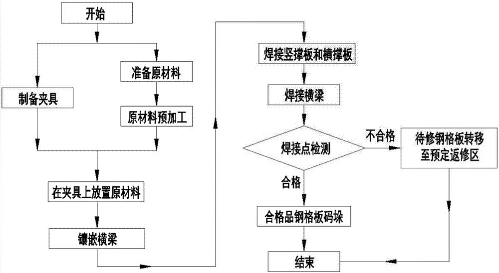
[0035] The invention provides an automatic manufacturing method for a steel grating, such as Figure 1 to Figure 6 shown, including the following steps:

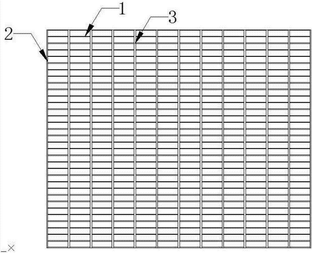
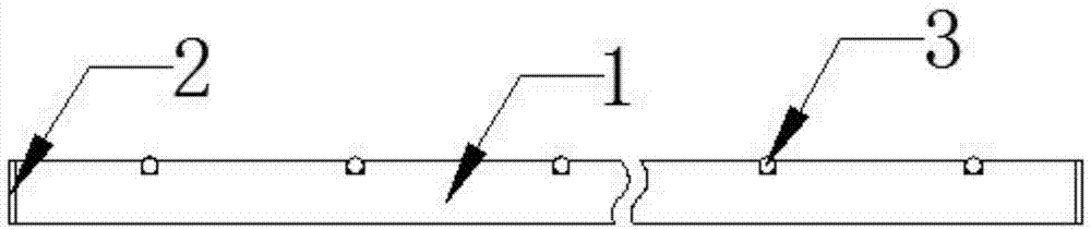
[0036] Step 1: Prepare raw materials: Prepare several vertical braces 1 of equal length, at least two horizontal braces 2 of equal length, and several beams 3 of equal length; further, the horizontal braces 2 and vertical braces 1 in Step 1 All flat steel. The crossbeam 3 in step 1 is rebar or twisted square steel. Further, the total number of cross braces 2 and vertical braces 1 is 34, of which there are two cross braces 2 and eleven cross beams 3 . Other specifications are the same.

[0037] Step 2: raw material pre-processing: using a punching machine to process several supporting grooves 4 with the same position, shape and size on one side edge of each vertical support pl...


PUM


Abstract

The invention provides an automatic manufacturing method of a steel grid plate. The automatic manufacturing method of the steel grid plate comprises the steps that raw materials and a clamp are prepared, wherein each raw material is connected in an interference fit manner and then is installed on the clamp in an embedded manner; the installed raw materials and the clamp are placed on an annular conveying device B, and welding nozzles are driven through mechanical devices to conduct welding on all the welding points; and the welding points of the welded finished steel grid plates are detected,the finished steel grid plates are classified into qualified steel grid plates and steel grid plates to be repaired, and then treatment is correspondingly conducted on the qualified steel grid platesand the steel grid plates to be repaired. By the adoption of the technical scheme, since flat steel is machined and formed through a punching machine, and the flat steel and cross beams are both reasonably located on the clamp, during welding, heat generated by welding has little influence on the manufacturing precision of the finished steel grid plates, it is guaranteed that the dimensions and shapes of the finished steel grid plates are identical, the machining precision is guaranteed, the yield of the finished steel grid plates is improved, the labor intensity is lightened, the production efficiency and quality are improved, the operation environment is improved, and the production cost is reduced.

Description

technical field [0001] The invention relates to the technical field of manufacturing steel gratings, in particular to an automatic manufacturing method for steel gratings. Background technique [0002] Steel grating, also known as grid plate, is a kind of steel product that is cross-arranged with flat steel according to a certain spacing and cross bars, and welded into a square grid in the middle. Steel grating is mainly used as a gutter cover, steel structure Platform boards, steel ladder pedal boards, etc. Steel gratings have ventilation, lighting, heat dissipation, anti-skid, explosion-proof and other properties. At present, the production of steel gratings is mainly produced by large-scale professional welding equipment. Steel top, and then implement pressure welding on the cross bar to weld the cross bar and flat steel into shape. This welding equipment has complicated equipment and a large impact on the power grid, and the initial equipment investment is huge; in the p...

Claims


Application Information

Patent Timeline
IPC IPC(8): B23P15/00
CPCB23P15/00
Inventor 张文安
Owner 张文安
Features
  • R&D
  • Intellectual Property
  • Life Sciences
  • Materials
  • Tech Scout
  • Unparalleled Data Quality
  • Higher Quality Content
  • 60% Fewer Hallucinations
Learn More