Furnace inlet circulation frame for glass mold annealing

A glass mold, turnover frame technology, applied in furnaces, heat treatment furnaces, manufacturing tools, etc., can solve the problems of occupying space, reducing the contact area between the bottom surface of the mold and the bottom of the frame, and loading the glass mold into the material frame, so as to improve work efficiency. The effect of efficiency

Pending Publication Date: 2018-04-06
CHANGSHU JIANHUA MOLD TECH
View PDF3 Cites 1 Cited by
  • Summary
  • Abstract
  • Description
  • Claims
  • Application Information

AI Technical Summary

Problems solved by technology

However, there are the following shortcomings: First, although the setting of the central column is beneficial to improve the support strength when the upper and lower layers of material frames are stacked, it not only takes up space, but also interferes with the placement of the workpiece; second, the spiral stretchable belt Although the structure can increase the deformation margin and prevent cracking during the thermal deformation of the material frame in the annealing furnace, it is difficult to guarantee the overall rigidity; The required design of the workpiece to be annealed makes it impossible to load the glass mold with the matching structure of the two halves of the mold to be annealed into the material frame, because the annealing uniformity of the glass mold in a vertical state and placed in the frame in a single layer is ideal In addition, vertical placement can also minimize the contact area between the bottom surface of the mold and the bottom of the frame; Fourth, it is not convenient for the stacking of the material frames, especially after stacking, because there is no interaction between the upper and lower material frames. As a containment measure, there is a risk of slippage

Method used


Image

  • Furnace inlet circulation frame for glass mold annealing
  • Furnace inlet circulation frame for glass mold annealing

Examples


Embodiment Construction

[0021] In order to understand the technical essence and beneficial effects of the present invention more clearly, the applicant will describe in detail the following examples, but the descriptions of the examples are not intended to limit the solutions of the present invention. Equivalent transformations that are only formal but not substantive should be regarded as the scope of the technical solution of the present invention.

[0022] In the following descriptions, all concepts involving directionality or orientation of up, down, left, right, front and rear are based on figure 1 As far as the position and state of the present invention are concerned, it cannot be understood as a special limitation on the technical solution provided by the present invention.

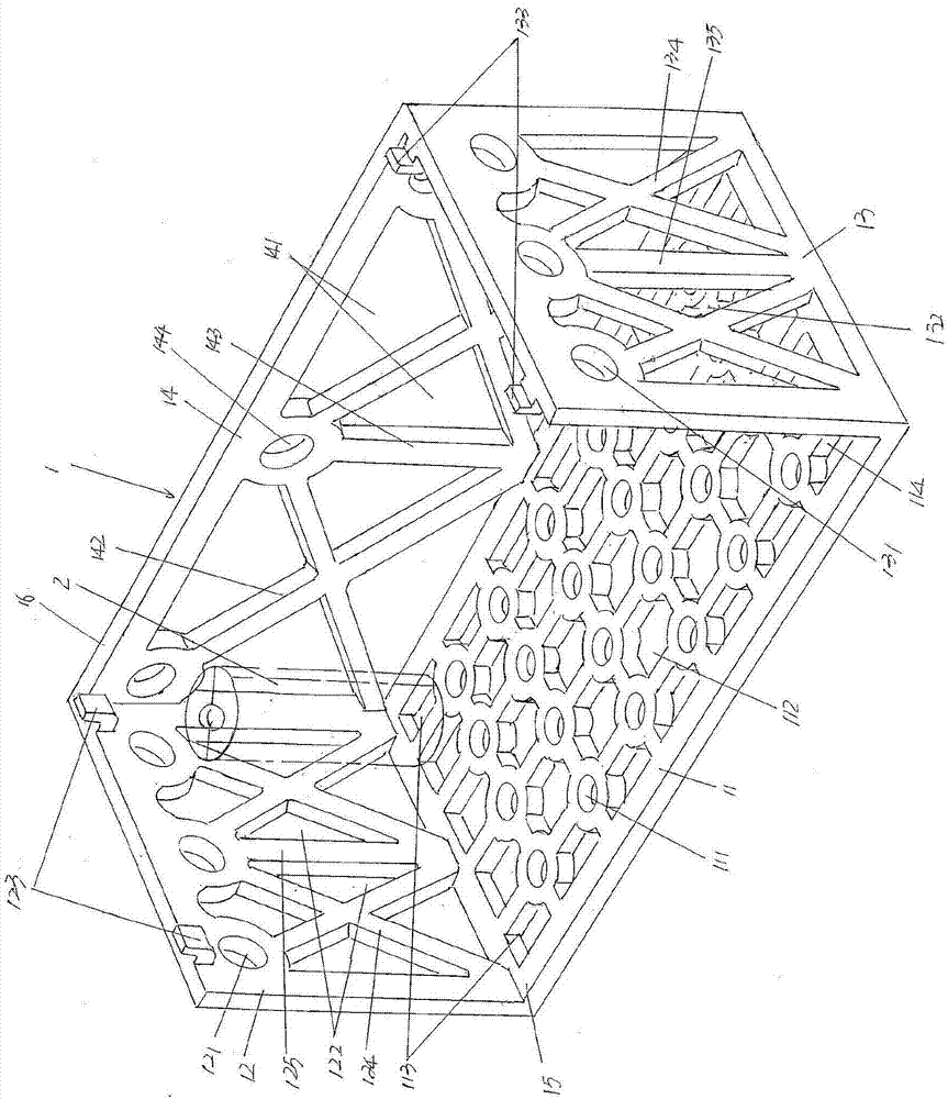
[0023] See figure 1 , shows a frame body 1, and this frame body 1 is made up of bottom frame sheet 11, left frame sheet 12, right frame sheet 13 and back frame sheet 14, and left frame sheet 12 is in the state perpendic...


PUM


Abstract

A furnace inlet circulation frame for glass mold annealing comprises a frame body composed of a bottom frame piece, a left frame piece, a right frame piece and a rear frame piece; the circulation frame is characterized in that a frame body front opening is formed in the front side of the frame body, a frame body top opening is formed in the top of the frame body, a bottom frame piece round heat transmitting cavity and a bottom frame piece polygonal heat transmitting cavity are formed in the bottom frame piece, a pair of left frame piece limiting foot bolt closing holes are formed in the left end of the bottom frame piece, a pair of right frame piece limiting foot bolt closing holes are formed in the right end of the bottom frame piece, left frame piece round and triangular heat transmitting cavities are formed in the left frame piece, a pair of left frame piece limiting feet are arranged on the upper portion of the left frame piece, the upper portions of the left frame piece limiting feet stretch out of the upper plane of the left frame piece, a right frame piece round heat transmitting cavity and a right frame piece triangular heat transmitting cavity are formed in the right framepiece, a pair of right frame piece limiting feet are arranged on the side, facing the left frame piece, of the upper portion of the right frame piece, the upper portions of the right frame piece limiting feet stretch out of the upper plane of the right frame piece, and a rear frame piece triangular heat transmitting cavity is formed in the rear frame body. Annealing quality is improved, work efficiency is high, accidents caused by collapsing are avoided, and a shovel car can conveniently carry out shovel transportation operation.

Description

technical field [0001] The invention belongs to the technical field of auxiliary facilities in the manufacture of glass molds, and in particular relates to a turnover frame for entering a furnace for annealing of glass molds. Background technique [0002] As known in the industry, the glass mold material is generally gray cast iron (referred to as "gray cast iron"). The heat treatment of gray cast iron can purposefully improve the matrix structure of cast iron through heating and cooling methods, so that it has the same structure as the obtained one. Corresponding performance to meet the requirements of the required process conditions. Annealing is an important way to further adjust and improve the matrix structure to improve the properties of cast iron. After the glass mold casting is formed, an annealing treatment at about 950°C is performed to change the matrix (but does not change the shape and distribution of graphite), and the pearlite content is reduced, while the fe...

Claims


Application Information

Patent Timeline
Patent Type & Authority Applications(China)
IPC IPC(8): C21D1/26C21D9/00
CPCC21D1/26C21D9/0025
Inventor 苏秋君胡兵朋马伟刚董磊王佳王乐乐
Owner CHANGSHU JIANHUA MOLD TECH
Why Eureka
Try Eureka