
Chemical incinerator for conveniently treating combustion waste gas and waste slag

A technology for burning waste gas and incinerators, applied in incinerators, combustion methods, combustion types, etc., can solve the problems of waste gas leakage, difficult discharge of waste residue, pollution of the environment, etc., to achieve reasonable structure, easy collection and discharge treatment, and prevention of leakage and discharge. Effect

Inactive Publication Date: 2018-04-06
登封市绿奥农林科技有限公司
View PDF0 Cites 7 Cited by
  • Summary
  • Abstract
  • Description
  • Claims
  • Application Information

AI Technical Summary

Problems solved by technology

[0002] Chemical incinerator is a kind of treatment equipment used for harmless treatment of medical waste. Its principle is to use coal, fuel oil, gas and other fuels to burn and carbonize the objects to be treated at high temperature to achieve the purpose of disinfection. , since the above-mentioned waste is mostly organic and carries a variety of germs, it cannot be directly landfilled, and can only be treated harmlessly through a special chemical incinerator
[0003] Due to the existence of feed inlet and slag discharge door in the chemical incinerators on the market, the waste gas produced by incineration often leaks, which not only pollutes the environment, but also makes it difficult to discharge the incinerated waste residue

Method used


Image

  • Chemical incinerator for conveniently treating combustion waste gas and waste slag
  • Chemical incinerator for conveniently treating combustion waste gas and waste slag
  • Chemical incinerator for conveniently treating combustion waste gas and waste slag

Examples


Embodiment Construction

[0022] In order to make the object, technical solution and advantages of the present invention more clear, the present invention will be further described in detail below in conjunction with the accompanying drawings and embodiments. It should be understood that the specific embodiments described here are only used to explain the present invention, not to limit the present invention.

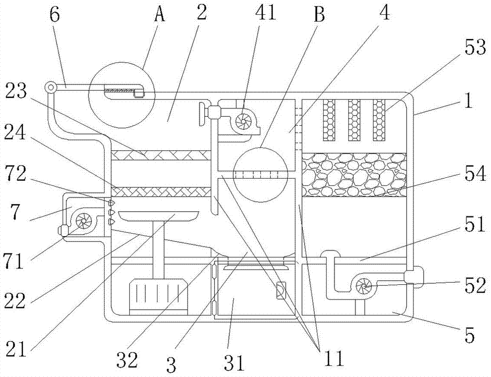
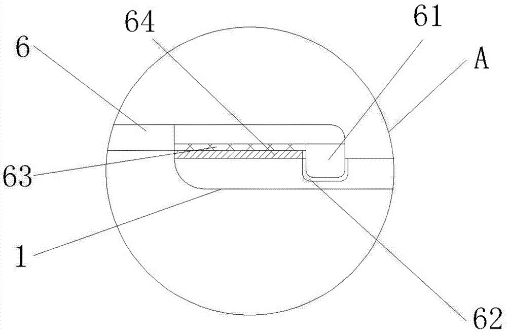
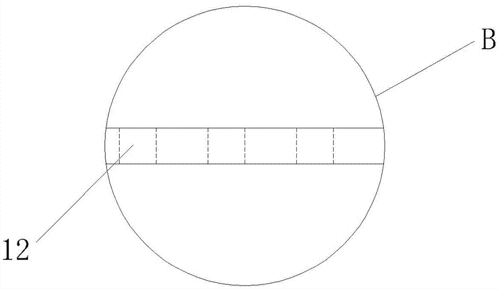
[0023] Such as Figure 1-3 As shown, a chemical incinerator that facilitates the treatment of combustion exhaust gas and waste slag includes a furnace body 1, and the interior of the furnace body 1 is separated by a partition 11 into a combustion chamber 2, a slag collection chamber 3, an exhaust gas recirculation chamber 4, and an exhaust gas treatment chamber 5. The waste gas return chamber 4 is located above the slag collection chamber 3, and the combustion chamber 2 and the waste gas treatment chamber 5 are located on both sides of the waste gas return chamber 4. The air holes 12 of the exh...


PUM


Abstract

The invention relates to a chemical incinerator which is convenient for treating combustion waste gas and waste slag. It includes a furnace body which is divided into a combustion chamber, a slag collection chamber, a waste gas recirculation chamber and a waste gas treatment chamber by a partition inside. The waste gas reflow chamber is respectively connected with the slag collection chamber and The exhaust gas treatment chamber is connected through the air holes on the corresponding partitions. The exhaust gas return chamber is equipped with a first exhaust fan, and the bottom of the exhaust gas treatment chamber is equipped with a second exhaust fan. The air inlet of the first exhaust fan is located in the combustion chamber, and the outlet of the second exhaust fan is The tuyere is connected with the outside; the bottom of the combustion chamber is connected with the slag collection chamber, and the bottom of the combustion chamber is provided with a downward-sloping deflector. There are first and second filter screens, and the mesh holes of the first filter screen are larger than the mesh holes of the second filter screen. The invention can process the harmful flue gas generated in the incineration process on the basis of fully incinerating the waste, prevent the gas from leaking out as much as possible, and also easily collect and discharge the waste slag generated by the combustion.

Description

technical field [0001] The invention belongs to the field of organic waste treatment devices, and in particular relates to a chemical incinerator which is convenient for treating combustion waste gas and waste residue. Background technique [0002] Chemical incinerator is a kind of treatment equipment used for harmless treatment of medical waste. Its principle is to use coal, fuel oil, gas and other fuels to burn and carbonize the objects to be treated at high temperature to achieve the purpose of disinfection. , since the above-mentioned wastes are mostly organic matter and carry a variety of germs, they cannot be directly landfilled, and can only be treated harmlessly through special chemical incinerators. [0003] Due to the existence of feed inlet and slag discharge door in the chemical incinerators on the market, the waste gas generated by incineration often leaks, which not only pollutes the environment, but also makes it difficult to discharge the incinerated waste re...

Claims


Application Information

Patent Timeline
IPC IPC(8): F23G5/08F23G5/44F23J1/00F23J15/02F23L5/02
CPCF23G5/08F23G5/44F23G2202/10F23G2204/101F23G2209/20F23J1/00F23J15/02F23J2215/10F23J2215/20F23J2219/30F23L5/02
Inventor 何振贤
Owner 登封市绿奥农林科技有限公司
Learn More