
Flameless combustion chamber for Stirling engine and implementation method of flameless combustion chamber

A Stirling engine and combustion chamber technology, applied in the combustion method, combustion chamber, continuous combustion chamber, etc., can solve the problems of high local temperature, long flame length, uneven temperature distribution, etc., to reduce the peak temperature and increase the zero temperature. Component life, the effect of ensuring long-term stable operation

Pending Publication Date: 2018-04-06
SHANGHAI MICROPOWERS
View PDF0 Cites 4 Cited by
  • Summary
  • Abstract
  • Description
  • Claims
  • Application Information

AI Technical Summary

Problems solved by technology

[0003] At present, the Stirling engine combustion chamber using liquid fuel has problems such as uneven temperature distribution, excessive local temperature, and excessively long flame length.

Method used


Image

  • Flameless combustion chamber for Stirling engine and implementation method of flameless combustion chamber
  • Flameless combustion chamber for Stirling engine and implementation method of flameless combustion chamber
  • Flameless combustion chamber for Stirling engine and implementation method of flameless combustion chamber

Examples


Embodiment approach

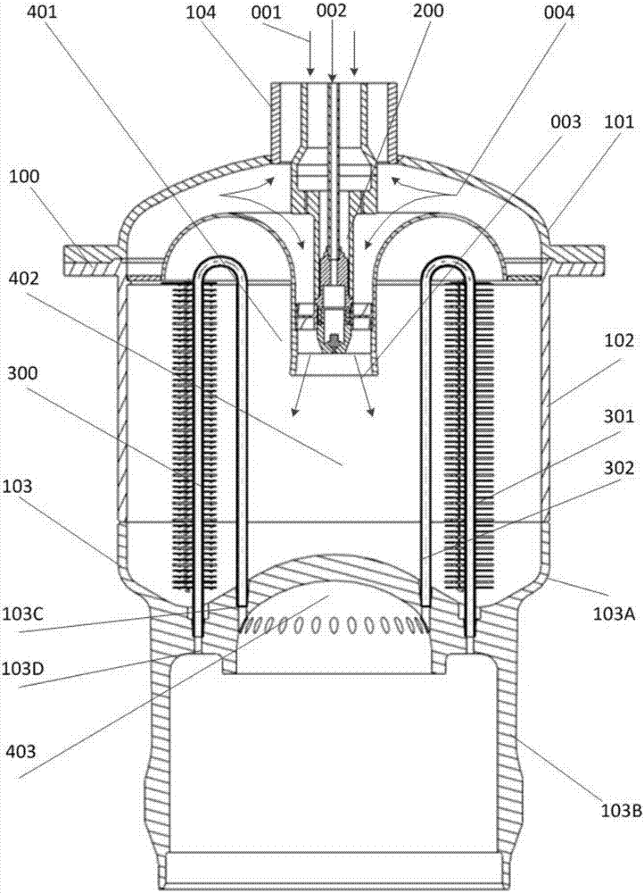
[0078] Also provided in the present invention is a kind of implementation method, the method that applies aforementioned implementation Stirling engine to use flameless combustion chamber 401 to implement, comprises the following steps:

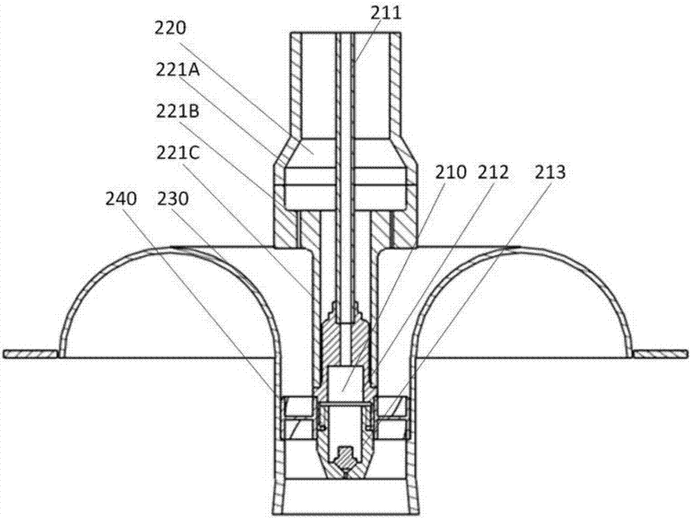
[0079] The oxidant 001 enters from the intake pipe assembly 220, the smoke 004 is drawn into the mixing pipe 230 for mixing, and the mixed gas flows through the swirler 240 to form a backflow in the combustion zone 402 in the housing 100;

[0080] The liquid fuel 002 enters from the fuel injector 210, and after being evaporated, it is mixed with the mixed gas flowing through the swirler 240 to form a combustible mixed gas. The heat exchanger 300 performs heat exchange. Part of the exchanged flue gas 004 flows out of the casing 100 from the exhaust pipe 104 , and the other part is entrained into the mixing pipe 230 to mix with the oxidant 001 entering from the intake pipe assembly 220 .

[0081] In this implementation method, it can be ensured...


PUM


Abstract

The invention discloses a flameless combustion chamber for a Stirling engine and an implementation method of the flameless combustion chamber. The flameless combustion chamber comprises a combustion chamber housing, a combustor and a heat exchanger; the housing consists of an upper housing part and a lower housing part; an exhaust pipe is arranged at the top of the housing; a heat exchanger barrelis arranged at the bottom of the housing; the lower housing part is connected with the top of the heat exchanger barrel into a whole; the top of the heat exchanger barrel, the lower housing part andthe upper housing part form a combustion chamber space; a hot cavity of the Stirling engine is formed in the lower end of the heat exchanger barrel; the top of the heat exchanger barrel separates thecombustion chamber from the hot cavity; the combustor and the heat exchanger are arranged in the housing from the top to the bottom sequentially; the heat exchanger comprises a circle of heat exchangepipes arranged in a reverse-U-shaped manner; and one ends of the heat exchange pipes communicate with the hot cavity of the Stirling engine, and the other ends of the heat exchange pipes communicatewith a reheater, thus a circuiting working medium system is formed. The implementation method comprises the step that the combustion chamber is used for combustion. The flameless combustion chamber and the implementation method have the characteristics that the combustion chamber is uniform in temperature, the combustion efficiency is high and the safety and reliability are achieved. The flamelesscombustion chamber is particularly suitable for the Stirling engine for use.

Description

technical field [0001] The invention relates to the technical field of a Stirling engine, in particular to a flameless combustion chamber for a Stirling engine and an implementation method thereof. Background technique [0002] Stirling Engine is a closed-loop regenerative cycle engine heated by external energy. It has the characteristics of high efficiency, low noise, low pollution and wide energy adaptability. The combustion chamber is an important part of the Stirling engine. Its function is to rationally organize combustion and heat exchange. The efficiency and reliability of the combustion chamber have an important impact on the performance of the Stirling engine. [0003] At present, the Stirling engine combustion chamber using liquid fuel has problems such as uneven temperature distribution, excessive local temperature, and excessively long flame length. Therefore, it is necessary to adopt more advanced combustion technology to further improve the efficiency and reli...

Claims


Application Information

Patent Timeline
IPC IPC(8): F23R3/58F23R3/16
CPCF23R3/16F23R3/58Y02E20/34
Inventor 兰健吕田黄晓宇陈东刘焜
Owner SHANGHAI MICROPOWERS
Learn More