Antenna-feed compact range device

A compact field, feed-type technology, applied in the direction of antenna support/installation device, antenna, antenna radiation pattern, etc., can solve the problem of difficult to deal with non-uniform settlement, deterioration of quiet zone quality, increase of reflector and overall positioning of feed source basic engineering Realization difficulty and manufacturing cost, etc., to achieve the effect of increasing engineering difficulty and manufacturing cost, improving profile accuracy, and improving plane wave quality

Pending Publication Date: 2018-04-06
BEIHANG UNIV
View PDF17 Cites 5 Cited by
  • Summary
  • Abstract
  • Description
  • Claims
  • Application Information

AI Technical Summary

Problems solved by technology

In addition, the ultra-large-scale compact field will increase the difficulty and manufacturing cost of the overall positioning of the reflective surface and the feed source, and it will be difficult to deal with the non-uniform settlement of the concrete foundation caused by non-uniform load, which will further cause the feed source to irradiate the reflective surface of the compact field out of focus Quiet zone quality deterioration

Method used


Image

  • Antenna-feed compact range device
  • Antenna-feed compact range device
  • Antenna-feed compact range device

Examples


Embodiment Construction

[0025] The present invention will be further described below in conjunction with the accompanying drawings and specific embodiments.

[0026] A preferred embodiment of the present invention:

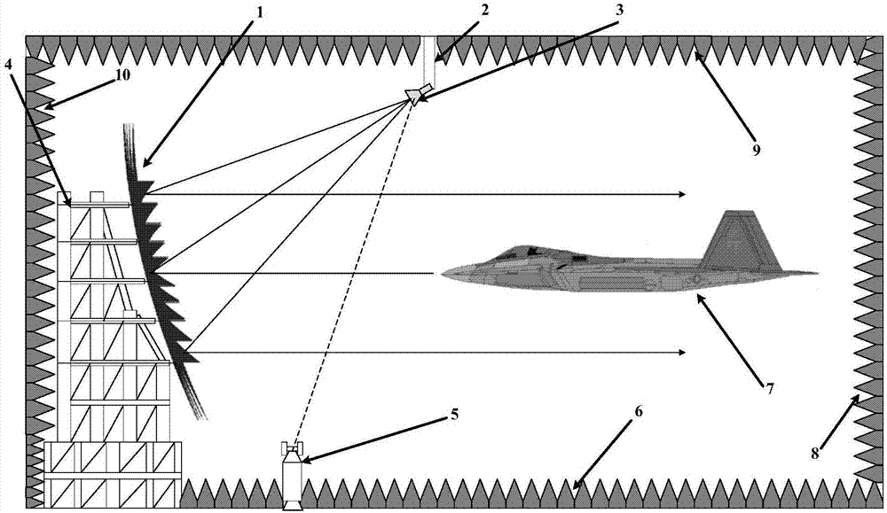
[0027] Such as figure 1 The antenna feeder compact field device shown includes the reflector 1 of the single reflector compact field, the feed source adaptive positioning device 2 of the antenna type compact field, the feed source 3 of the compact field, and the back frame structure 4 of the truss type compact field , a laser tracker for measuring the relative position of the feed source and the reflecting surface 5, the floor of the microwave anechoic room 6, the equipment to be tested in the quiet area of ​​the compact field 7, the rear wall of the microwave anechoic room 8, the ceiling of the microwave anechoic room installed with an antenna feed source 9 and the microwave anechoic room front wall 10, wherein,

[0028] The reflective surface 1 of the compact field of the single refl...


PUM


Abstract

The invention discloses an antenna-feed compact range device mainly composed of a compact range reflection surface, an adaptive positioning feed source, a laser tracker and a microwave darkroom. The compact range reflection surface is a quadric surface. An increase in the size of the reflection surface causes a quadratic increase in the two-dimensional bending offset of the reflection surface, andthus aggravates structural deformation and long-term creep caused by self-weight, and reduces the structural stability and the profile accuracy of the reflection surface system. According to the antenna-feed compact range device, the reflection surface is a recumbent structure, and the feed source is configured in antenna-feed arrangement, which is beneficial to improving the structural stabilityand the profile accuracy of a super large-scale compact range reflection surface system and the plane wave quality of a compact range dead zone.

Description

technical field [0001] The present invention relates to the technical field of compaction field, in particular to a highly stable antenna feeder type compaction field device, the overall structure adopts antenna feeder layout, the main purpose is to improve the stability of the structural system of the compaction field and reduce the ultra-large-scale compaction field Structural design and manufacturing are difficult, improving the plane wave quality and long-term stability of the quiet zone of ultra-large-scale compact fields, especially suitable for ultra-large compact fields with reflective surfaces exceeding 30m. Background technique [0002] With the large-scale and mass-produced large-scale electronic equipment, such as the installation and maintenance of full-scale aircraft and large-scale ship-borne phased array radar, the demand for precise measurement of full-scale radar target scattering and large-aperture antennas is becoming increasingly urgent. The traditional ...

Claims


Application Information

Patent Timeline
Patent Type & Authority Applications(China)
IPC IPC(8): G01R29/10H01Q19/13H01Q1/12
CPCH01Q1/12H01Q19/13G01R29/10
Inventor 李志平霍鹏武建华王正鹏
Owner BEIHANG UNIV
Why Eureka
Try Eureka