In-barrel compacting device for radioactive solid waste

A solid waste and radioactive technology, applied in radioactive purification, nuclear engineering, etc., can solve the problems of increasing the exposure of operators to radioactive pollution, large dimensions, and large floor space, etc., to achieve overall height reduction, small installation length, and occupied space. The effect of space reduction

Pending Publication Date: 2018-04-06
NO 719 RES INST CHINA SHIPBUILDING IND
View PDF1 Cites 4 Cited by
  • Summary
  • Abstract
  • Description
  • Claims
  • Application Information

AI Technical Summary

Problems solved by technology

[0003] At present, the traces of low-level radioactive waste produced by nuclear facilities at home and abroad are basically packaged by compaction and volume reduction. Most of the compaction equipment in barrels at home and abroad are driven by oil cylinders, which need to be equipped with a large and complex hydraulic system, and the equipment has large dimensions; Many positions are set next to the equipment, which increases the possibility of operators being exposed to radioactive contamination
For example, CN202573035U uses an oil cylinder to drive vertical lifting for compaction, and a return oil tank is set on the frame, and the sliding block for entering and exiting the barrel and the lifting door are driven by an air cylinder. Not only the hydraulic system needs to be configured, but also an additional air source is required. The pipeline is complicated and occupies a lot of space. It is large and inconvenient for later maintenance; it sets the feeding door on the feeding panel of the device, although the feeding process is simplified, the operator still needs to perform feeding beside the device

Method used


Image

  • In-barrel compacting device for radioactive solid waste
  • In-barrel compacting device for radioactive solid waste

Examples


Embodiment Construction

[0026] In order to make the technical features, features, technical effects and design purposes of the present invention more obvious and understandable, the present invention will be further elaborated below in conjunction with the accompanying drawings and specific implementation methods.

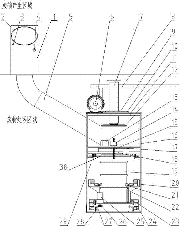
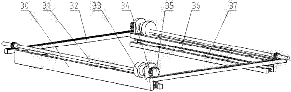
[0027] Such as figure 1 and 2 As shown, the embodiment of the present invention provides a compacting device in a solid radioactive waste barrel, including:

[0028] Frame 11, the side panel of described frame 11 is provided with waste chute 5, and waste chute 5 communicates with feed inlet 1, and described feed inlet 1 is provided with lid 2 that can be opened and closed up and down, and after lid 2 covers airtight;

[0029] The front panel of the frame 11 is provided with an inlet and outlet barrel mouth, and the inlet and outlet barrel mouth is provided with a flashboard door 29, and the frame on both sides of the flashboard door 29 is provided with a guide groove 16, and the flashbo...


PUM


Abstract

The invention relates to a solid waste compacting device, and provides an in-barrel compacting device for radioactive solid wastes used in small space. The device comprises a rack, a feed opening arranged on a waste generating region, a waste slide communicating the rack and the feed opening, a damper gate of a rack in-and-out barrel panel, a linear guide rail arranged on the bottom of the rack todelivery in and out a steel barrel, a multi-stage electric cylinder which is on the top of the rack and is connected with a compacting disk, a high-pressure vortex fan which is on a corner of the topof the rack and is connected with an exhaust port, a garbage bag holding box in the rack, an automatic bag cutting and sealing mechanism, and a 200L steel barrel. The device is convenient in operation, proper in appearance dimensions, and high in reliability, and effectively reduces generation of secondary wastes, and reduces contact of workers on radioactive contamination.

Description

technical field [0001] The invention relates to a waste compacting device, in particular to a radioactive solid waste internal compacting device used in a small space. Background technique [0002] A large number of labor insurance products will be produced during the operation, maintenance and decommissioning of different nuclear facilities, and these labor insurance products will have different degrees of radioactive pollution. If the radioactive dose exceeds the recyclable standard, these labor insurance products containing traces of low radioactivity will be What has no use value becomes waste. These wastes cannot be equated with wastes that have not been radioactively contaminated. They can be simply shredded-packaged-stored or incinerated without special control, while wastes that have been subjected to trace amounts of radioactive contamination need to be classified separately and processed in separate equipment. It needs to be isolated and temporarily stored separat...

Claims


Application Information

Patent Timeline
Patent Type & Authority Applications(China)
IPC IPC(8): G21F9/36
CPCG21F9/36
Inventor 范卓张宇毛宏勇姜勇
Owner NO 719 RES INST CHINA SHIPBUILDING IND
Why Eureka
Try Eureka