An electric motor for driving an ABB system

A technology of ABS system and electric motor, applied in the direction of electric components, synchronous motor with stationary armature and rotating magnet, manufacturing motor generator, etc., can solve problems such as limitations, achieve manufacturability, high efficiency, reduce Effect of small risk of demagnetization

Inactive Publication Date: 2018-04-06
ROBERT BOSCH GMBH
View PDF16 Cites 5 Cited by
  • Summary
  • Abstract
  • Description
  • Claims
  • Application Information

AI Technical Summary

Problems solved by technology

In this case, however, DC motors equipped with brushes encounter technical limitations with regard to the corresponding mechanical po

Method used


Image

  • An electric motor for driving an ABB system
  • An electric motor for driving an ABB system
  • An electric motor for driving an ABB system

Examples


Embodiment Construction

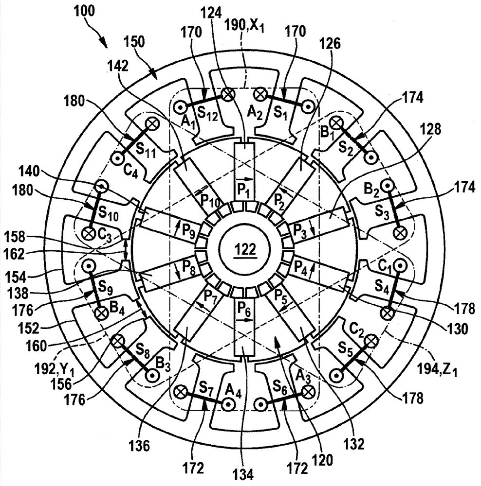
[0034] figure 1 An electric motor 100 , which is embodied as an example of an inner rotor motor with an inner rotor 120 and an outer stator 150 , is shown. The inner rotor 120 is preferably rotatably mounted on a rotor shaft 122 and coaxially surrounded by an outer stator 150 . In the ensuing description, the inner rotor 120 is simply referred to as the concept "rotor", and the outer stator 150 is simply referred to as the term "stator".

[0035] It is pointed out below that, figure 1 The electric motor 100 is shown only in principle, because the basic structure and function of suitable electric motors are well known from the prior art, thus for the sake of brevity and simplicity of the description, a detailed description of the electric motor 100 is omitted here. instruction of. Furthermore, it should be pointed out that the electric motor 100 is only shown as an example and is not intended to limit the invention as an inner rotor motor. It should also be mentioned that t...


PUM


Abstract

The invention relates to an electric motor (100) for driving an ABB system in a motor vehicle. The electric motor comprises a permanently-excited inner rotor (120) and an outer stator (150). The outerstator (150) has at least twelve stator teeth (S1-12). The inner rotor (12) has poles (P1-10) with a preset number, which are spaced from one another uniformly on the circumferential side. The numberof the poles is corresponding to a number obtained by subtracting integer multiples of two from the number of the stator teeth (S1-12) and the poles (P1-10) which are spaced from one another uniformly on the circumferential side are constructed like spokes for concentrating corresponding magnetic flux.

Description

technical field [0001] The invention relates to an electric motor for driving an ABS system in a motor vehicle, the electric motor having a permanently excited inner rotor and an outer stator. Background technique [0002] Motor vehicles with an ABS system (Anti-Blocker System: Anti-lock Brake System) are known from the prior art, in which a DC motor with brushes is used. In order to reduce the corresponding reaction time of such motor vehicles up to complete braking in the event of unforeseen obstacles, especially in the context of motor vehicles that operate at least semiautonomously, it is necessary to increase the Corresponding flow rate of hydraulic brake fluid. In this case, however, DC motors equipped with brushes encounter technical limitations with regard to the corresponding mechanical power to be captured, in particular with regard to torque, without correspondingly tolerating a significantly increased current consumption. Contents of the invention [0003] Th...

Claims


Application Information

Patent Timeline
IPC IPC(8): H02K1/08H02K15/085H02K1/27H02K1/14H02K3/28
CPCH02K1/08H02K1/146H02K1/2773H02K3/28H02K15/085H02K2213/03H02K21/16H02K1/14H02K1/27
Inventor S.A.埃文斯C.屈尔斯海默D.苏亚雷斯-塞米纳里奥J.魏德利希L.杜里克斯M.彼得斯W.雷布
Owner ROBERT BOSCH GMBH
Why Eureka
Try Eureka