Inverter, method for controlling inverter and control device

A technology of inverters and switching tubes, applied in the field of control inverters and inverters, can solve the problems of low efficiency, large switching loss and on-state loss of switching devices, etc.

Active Publication Date: 2018-04-06
EMERSON NETWORK POWER CO LTD
View PDF8 Cites 14 Cited by
  • Summary
  • Abstract
  • Description
  • Claims
  • Application Information

AI Technical Summary

Problems solved by technology

[0011] However, the applicant found that although the 3L-NPC topology or the 3L-ANPC topology has been widely used in the field of power electronics, the efficiency is not high due t

Method used


Image

  • Inverter, method for controlling inverter and control device
  • Inverter, method for controlling inverter and control device
  • Inverter, method for controlling inverter and control device

Examples


Embodiment Construction

[0076] In order to provide an implementation plan for improving the efficiency of the inverter, the embodiment of the present invention provides an inverter, a method and a device for controlling the inverter. The preferred embodiments of the present invention will be described below in conjunction with the accompanying drawings. It should be understood that , the preferred embodiments described here are only used to illustrate and explain the present invention, not to limit the present invention. And in the case of no conflict, the embodiments in the present application and the features in the embodiments can be combined with each other.

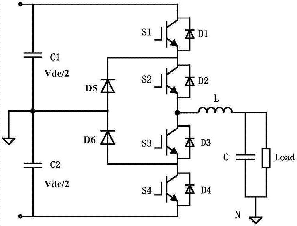
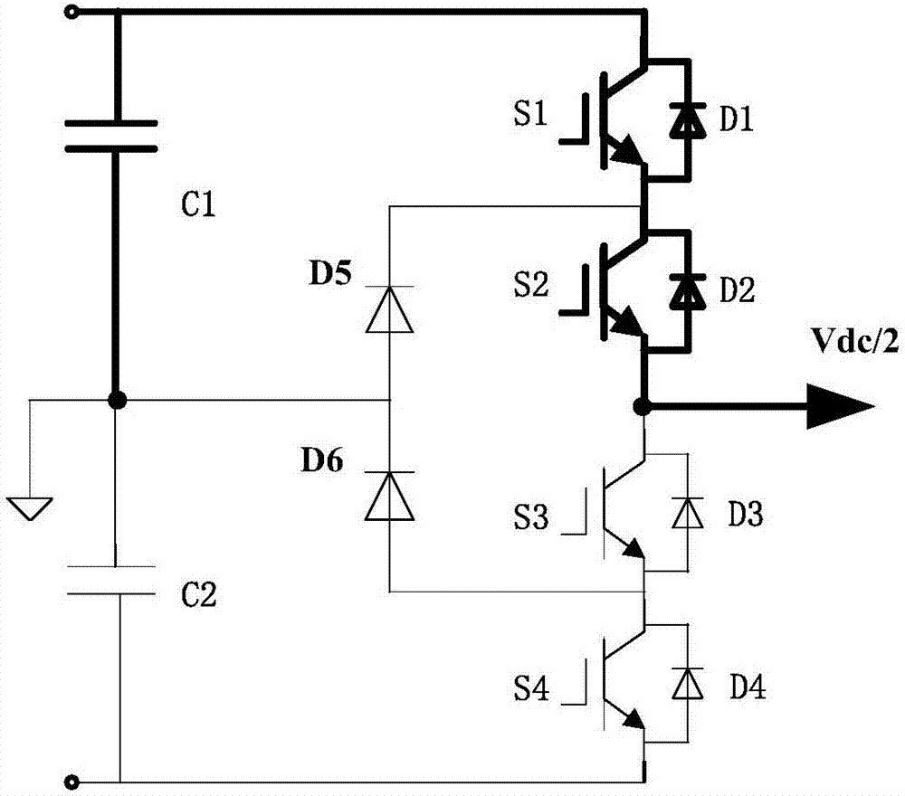
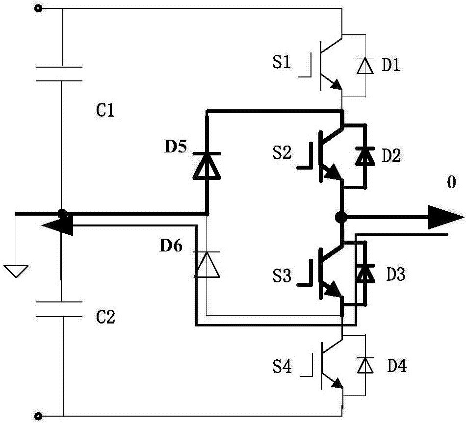
[0077] Such as Figure 4 As shown, it is a schematic structural diagram of the inverter provided by the embodiment of the present application, including an active clamping three-level topology, a seventh switch tube S7, an eighth switch tube S8, a diode D7 corresponding to the seventh switch tube S7, and A diode D8 corresponding to the eig...


PUM


Abstract

The present invention provides an inverter, a method and device for controlling the inverter. The invention aims to improve the efficiency of the inverter. The inverter comprises an active clamping three-level topological structure comprising a first bus-bar capacitor, a second bus-bar capacitor and an inverter circuit. The inverter circuit includes a first switching tube, a second switching tube,a third switching tube, a fourth switching tube, a fifth switching tube and a sixth switching tube; the first switching tube, the second switching tube, the third switching tube and the fourth switching tube are sequentially connected in series in the same direction between a positive direct-current bus-bar and a negative direct-current bus-bar; the fifth switching tube and the sixth switching tube are connected in series in same direction; one end of the fifth switching tube and the sixth switching tube is connected with the series connection point of the first switching tube and the secondswitching tube, and the other end of the fifth switching tube and the sixth switching tube is connected with the series connection point of the third switching tube and the fourth switching tube; theseries connection point of the fifth switching tube and the sixth switching tube is connected with the series connection point of the first bus-bar capacitor and the second bus-bar capacitor; and eachswitching tube is in reverse parallel connection with one corresponding diode. The inverter also comprises a seventh switching tube and an eighth switching tube; the seventh switching tube and the eighth switching tube are connected in series in the same direction between the positive direct-current bus-bar and the negative direct-current bus-bar; the series connection point of the seventh switching tube and the eighth switching tube is connected with the series connection point of the second switching tube and the third switching tube; and the seventh switching tube and the eighth switchingtube are in reverse parallel connection with corresponding diodes.

Description

technical field [0001] The present invention relates to the technical field of power electronics, in particular to an inverter, a method and a device for controlling the inverter. Background technique [0002] With the continuous development of power electronics technology, Pulse Width Modulation (Pulse Width Modulation, PWM) has gradually become the mainstream control method of power electronic converters. Inverters and motor converters are more and more widely used. [0003] In terms of the number of phase voltage levels output by the PWM-modulated inverter, the inverter can be divided into two-level inverters, three-level inverters, five-level inverters, and multi-level inverters. In terms of implementation complexity, it is difficult to implement multi-level inverters with five levels and more. At present, two-level and three-level inverters are widely used in the industry. [0004] The two-level inverter is relatively simple to implement and the cost is low, but since...

Claims


Application Information

Patent Timeline
IPC IPC(8): H02M7/487H02M7/5387H02M7/5395
CPCH02M7/487H02M7/53873H02M7/5395H02M1/0054Y02B70/10H02M1/0095H02M7/219H02M7/5388H02M7/217H02J3/38H02J7/35H02M7/48H02M7/5387H02P6/04H02P27/06
Inventor 徐福斌张永辉邴阳
Owner EMERSON NETWORK POWER CO LTD
Why Eureka
Try Eureka