Power system equipment state monitoring method

A technology of equipment status and power system, applied in general control systems, control/regulation systems, electrical program control, etc. Strong anti-interference effect

Inactive Publication Date: 2018-04-10
田喜桂
View PDF0 Cites 5 Cited by
  • Summary
  • Abstract
  • Description
  • Claims
  • Application Information

AI Technical Summary

Problems solved by technology

[0004] The technical problem to be solved by the present invention is that the detection signals of many power equipment are transmitted by wired light signals, which greatly limits the monitoring range, laying limited transmission lines wastes manpower and material resources during use, and is inconvenient. The purpose is to provide power system equipment status monitoring The method solves the problem that the detection signals of many electric equipment are transmitted by wired optical signals, which greatly limits the monitoring range, and laying limited transmission lines wastes manpower and material resources during use, and is inconvenient.

Method used


Image

  • Power system equipment state monitoring method
  • Power system equipment state monitoring method

Examples


Embodiment

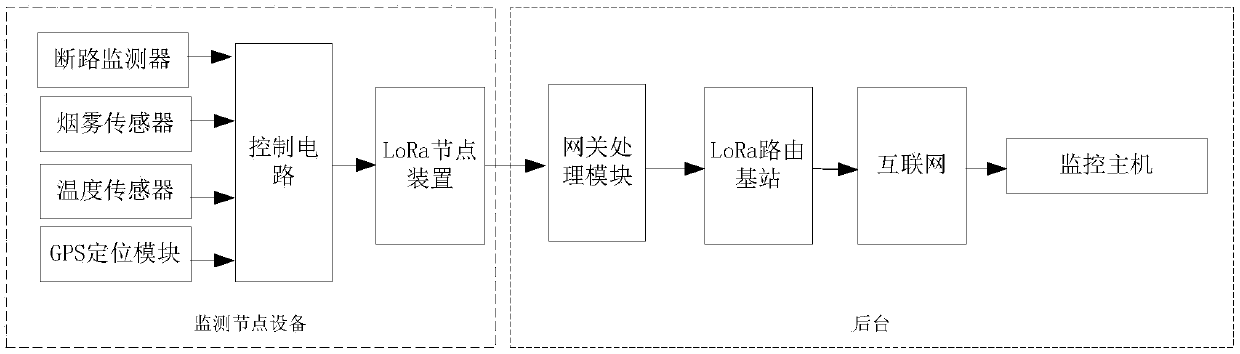
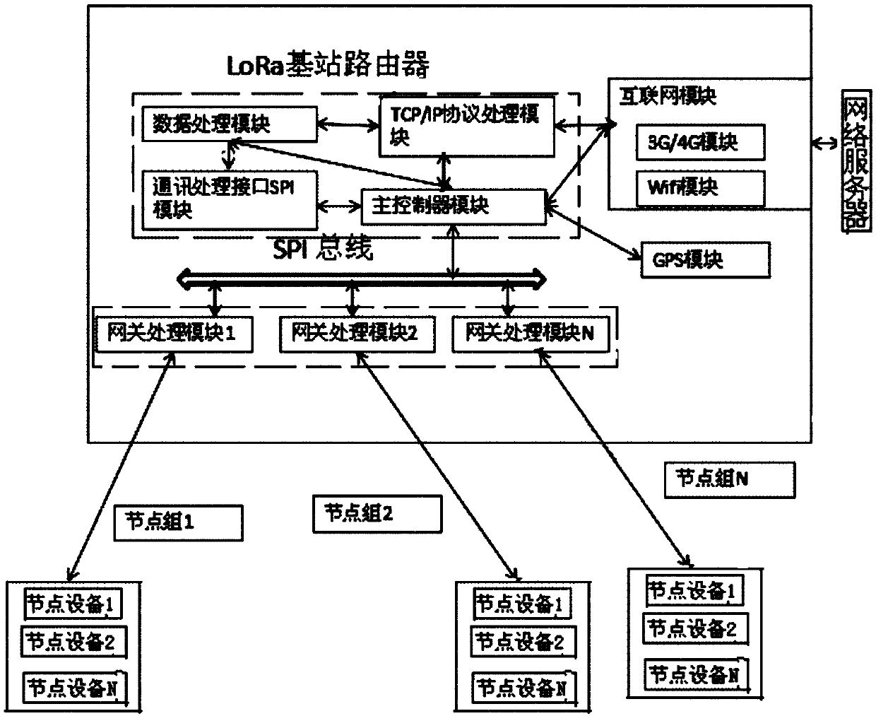
[0018] Such as figure 1 , figure 2 As shown, the power system equipment status monitoring method of the present invention installs monitoring equipment on the power equipment lines that need to be monitored, and the monitoring equipment transmits information to the background wirelessly; the monitoring equipment includes a circuit breaker monitor, a GPS positioning module, Control circuit, LoRa node device, disconnection monitoring equipment monitors the power state of electrical equipment and transmits the monitored state information to the control circuit. GPS positioning module is used to locate the detected position information and transmit the information to the control circuit. The control circuit will receive The information is transmitted to the LoRa node device; the background includes a gateway processing module, the gateway processing module is connected to the LoRa routing base station, the LoRa routing base station is connected to the Internet, the monitoring host ...


PUM


Abstract

The invention discloses a method for monitoring the state of power system equipment. Monitoring equipment is installed on the power equipment line required for monitoring, and the monitoring equipment transmits information to the background in a wireless manner; the monitoring equipment includes an open circuit monitor, a GPS positioning module, a Circuits, LoRa node devices, smoke sensors, and temperature sensors can monitor whether the equipment is abnormally powered off through the open circuit monitor, so as to achieve the purpose of monitoring. The monitoring equipment can monitor the internal smoke and fire status of the monitored power equipment through the smoke sensor , which is more advanced than the traditional external fire alarm system to monitor the fire situation. The LoRa communication circuit has the characteristics of long distance, low power consumption, multi-node, low cost, stable transmission, and strong anti-interference, so that the monitoring equipment The use range is wider, and its laying is simple, and node equipment can be added at will, so that the system has a larger capacity and a wider use range.

Description

Technical field [0001] The invention relates to power equipment monitoring, in particular to a method for monitoring the state of power system equipment. Background technique [0002] The traditional method of power equipment condition monitoring is regular manual inspection and regular preventive maintenance and testing. During the operation of the equipment, the personnel on duty frequently patrol the equipment, make judgments based on appearance phenomena, indicating instruments, etc., to find possible abnormalities to avoid accidents; in addition, the equipment is regularly inspected to stop operation, and preventive insulation tests and mechanical actions are performed. Test, deal with structural defects in time, etc. This system of frequent inspections and regular inspections plays an important role in ensuring the safe operation of power equipment. [0003] With the development of sensor technology and Internet of Things technology, the state monitoring methods of power eq...

Claims


Application Information

Patent Timeline
Patent Type & Authority Applications(China)
IPC IPC(8): G05B19/418G08B17/06G08B17/10
CPCG05B19/4185G08B17/06G08B17/10
Inventor 田喜桂
Owner 田喜桂
Why Eureka
Try Eureka