Single winding hybrid excitation magnetic lead screw

A hybrid excitation and magnetic screw technology, applied in the direction of permanent magnet clutch/brake, can solve the problems of low utilization rate of excitation winding, low thrust density, complex structure, etc., and achieve simple and compact, high thrust density, simple system structure compact effect

Active Publication Date: 2018-04-10
HARBIN INST OF TECH
View PDF6 Cites 15 Cited by
  • Summary
  • Abstract
  • Description
  • Claims
  • Application Information

AI Technical Summary

Problems solved by technology

[0008] The purpose of the present invention is to solve the problems of low thrust density, complex structure and low utilization rate of the excitation winding in the existing hybrid magnetic circuit magnetic screw, and to provide a single-winding hybrid excitation magnetic screw

Method used


Image

  • Single winding hybrid excitation magnetic lead screw
  • Single winding hybrid excitation magnetic lead screw
  • Single winding hybrid excitation magnetic lead screw

Examples


specific Embodiment approach 1

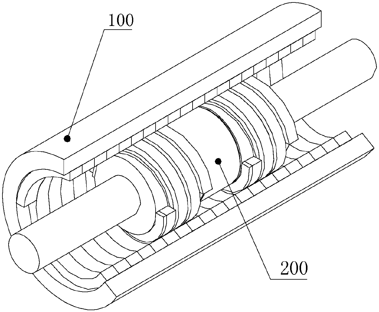
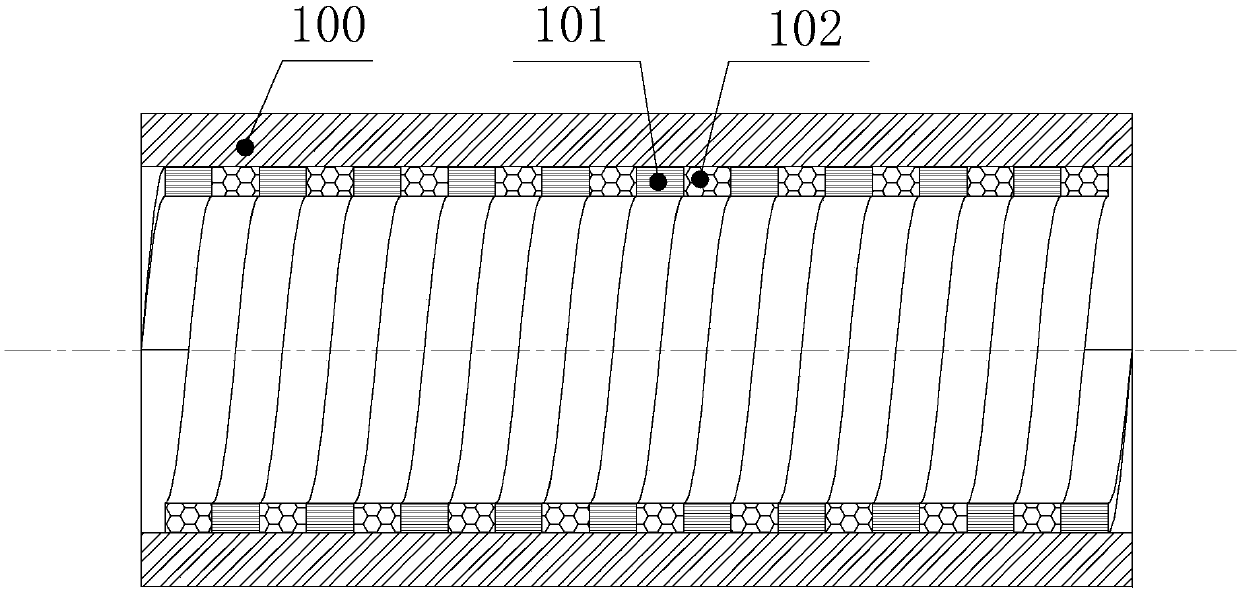
[0068] Specific implementation mode one: combine Figure 1 to Figure 5 This embodiment is described. In the single-winding hybrid excitation magnetic force lead screw described in this embodiment,

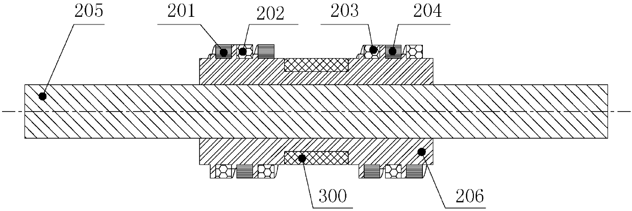
[0069] The magnetic screw 200 includes a first screw helical permanent magnet 201, a second screw helical permanent magnet 202, a third screw helical permanent magnet 203, a fourth screw helical permanent magnet 204, a first main shaft 205 and a first screw electrical iron ring 206 ;

[0070] The first screw electrical iron ring 206 is set on the first main shaft 205 and is fixedly connected with the first main shaft 205. The side wall of the first screw electrical iron ring 206 is provided with a circle of circumferential grooves 207, and the circumferential grooves 207 are used to place the annular excitation winding 300;

[0071] A helical groove 208 is formed on the sidewall of the first screw electrical iron ring 206 on the left and right sides of the circumferential groove ...

specific Embodiment approach 2

[0077] Specific implementation mode two: see Figure 1 to Figure 5 This embodiment is described. The difference between this embodiment and the single-winding hybrid excitation magnetic lead screw described in Embodiment 1 is that the polarities of the second screw helical permanent magnet 202 and the third screw helical permanent magnet 203 are opposite.

specific Embodiment approach 3

[0078] Specific implementation mode three: see Figure 1 to Figure 5 This embodiment is described. The difference between this embodiment and the single-winding hybrid excitation magnetic lead screw described in Embodiment 1 is that the heights of adjacent spiral salient poles 209 on the spiral groove 208 are different.


PUM


Abstract

The invention discloses a single winding hybrid excitation magnetic lead screw and belongs to the field of electromechanical transmission. The invention solves the problems of low thrust density, complex structure, and low utilization of an excitation winding of an existing hybrid magnetic circuit magnetic lead screw. The single winding hybrid excitation magnetic lead screw includes a magnetic nutand a magnetic screw, both of which are provided with spiral permanent magnets, and also includes an annular excitation winding. The magnetic nut coaxially sleeves the outside of the magnetic screw and an air gap is left therebetween. The annular excitation winding is fixed on the magnetic nut or the magnetic screw, for adjusting a coupling magnetic field of the air gap so as to adjust the thrustacting on the magnetic nut and the magnetic screw and finally complete the mutual transformation of linear motion and rotary motion. The single winding hybrid excitation magnetic lead screw of the invention is mainly for use on the electromechanical transmission.

Description

technical field [0001] The invention relates to a single-winding hybrid excitation magnetic force lead screw, which belongs to the field of electromechanical transmission. Background technique [0002] The permanent magnet magnetic screw can realize the mutual transformation of linear motion and rotary motion through magnetic field coupling. It has the advantages of high thrust density, high reliability, and overload protection. It has broad applications in the fields of aerospace, marine power generation, and artificial heart. prospect. Both the nut and the screw of the permanent magnet magnetic lead screw use permanent magnets as the excitation source, the air gap magnetic field is difficult to adjust, and the thrust is only related to the relative position between the nut and the screw. When the load changes, the relative position between the nut and the screw will also change, which will cause the speed of the system to fluctuate, which limits the application of the mag...

Claims


Application Information

Patent Timeline
IPC IPC(8): H02K49/10
Inventor 王骞高放李勇赵博
Owner HARBIN INST OF TECH
Why Eureka
Try Eureka