Intelligent electronic equipment cutting device

A technology of intelligent electronic equipment and cutting device, applied in the field of intelligent electronic equipment cutting device, can solve problems such as harm to human health, reduce work efficiency, and poor straight-line cutting, and achieve the effect of improving cutting quality, saving physical strength and saving time

Inactive Publication Date: 2018-04-13
成都弘硅科技有限公司
0 Cites 0 Cited by

AI-Extracted Technical Summary

Problems solved by technology

[0005] Aiming at the deficiencies of the prior art, the present invention provides a cutting device for intelligent electronic equipment, which solves...

Abstract

The invention discloses a cutting device for intelligent electronic equipment, which includes a support plate, a chute matching with a roller is provided on the top of the support plate, and support legs are fixedly connected to both sides of the bottom of the support plate. It relates to the technical field of electronic equipment. This cutting device for intelligent electronic equipment is connected with rollers slidingly on one side of the top of the support plate, so the worktable will always keep moving in a straight line, and the cutting will not be carried out by hand pushing, which will greatly save the physical strength of the staff and also save energy. More time, one end of the output shaft of the forward and reverse motor is fixedly connected with a gear, and the top of the gear is connected with a rack. When the cutting work is in progress, the motor is turned on, and the gear drives the rack to move left and right, making cutting more efficient. Fast, left and right movement, the cutting blade will move left and right to cut, so that the target can achieve the cutting effect in a short time, which greatly improves the work efficiency.

Technology Topic

Intelligent electronic deviceGear drive +3

Image

  • Intelligent electronic equipment cutting device
  • Intelligent electronic equipment cutting device
  • Intelligent electronic equipment cutting device

Examples

  • Experimental program(1)

Example Embodiment

[0021] The technical solutions in the embodiments of the present invention will be clearly and completely described below with reference to the accompanying drawings in the embodiments of the present invention. Obviously, the described embodiments are only a part of the embodiments of the present invention, but not all of the embodiments. Based on the embodiments of the present invention, all other embodiments obtained by those of ordinary skill in the art without creative efforts shall fall within the protection scope of the present invention.
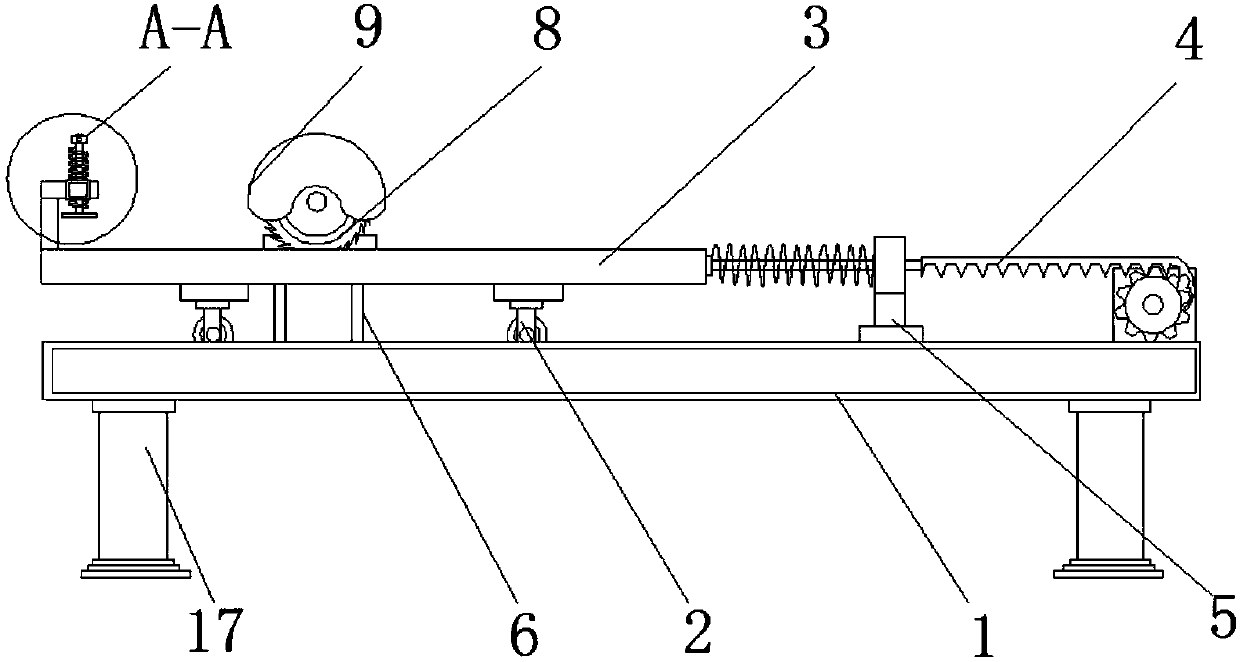
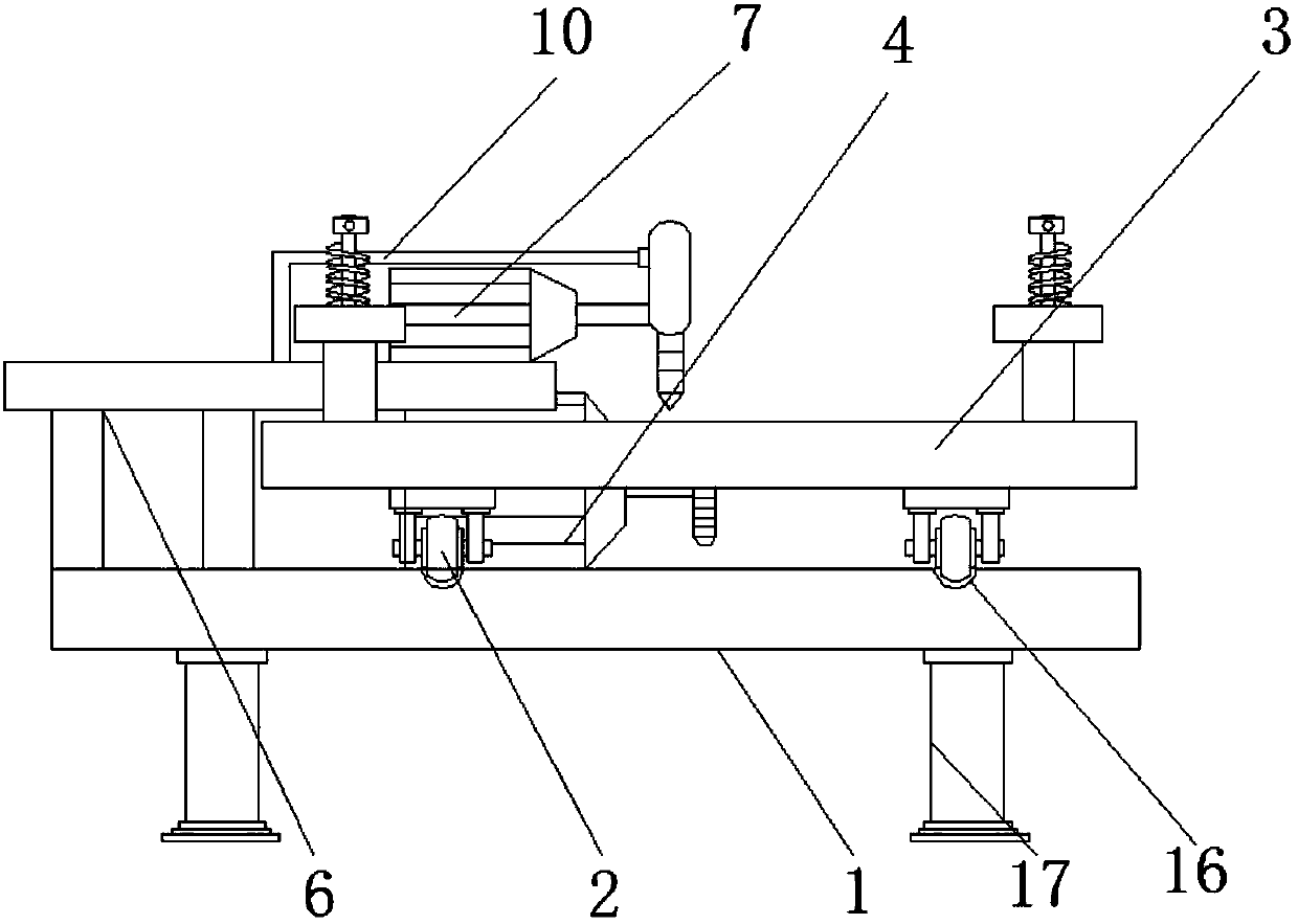
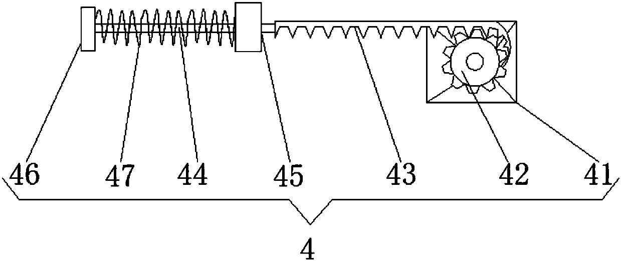
[0022] see Figure 1-4 , the present invention provides a technical solution: an intelligent electronic equipment cutting device, comprising a support plate 1, the top of the support plate 1 is provided with a chute 16 adapted to the roller 2, and both sides of the bottom of the support plate 1 are fixedly connected There are support legs 17, the top side of the support plate 1 is slidably connected with the roller 2, the top of the roller 2 is fixedly connected with the workbench 3, and the other side of the top of the support plate 1 is fixedly connected with a push device 4, and the push device 4 includes positive and negative. The rotary motor 41, one end of the output shaft of the forward and reverse rotation motor 41 is fixedly connected with a gear 42, the top of the surface of the gear 42 is driven and connected with a rack 43, one side of the rack 43 is fixedly connected with one side surface of the gear 42, the rack 43 The other side of the movable rod 44 is fixedly connected with a movable rod 44, the end of the movable rod 44 away from the rack 43 runs through a fixed block 45, and the end of the movable rod 44 extending to the side of the fixed block 45 is fixedly connected with a pull plate 46, and the surface of the movable rod 44 And a spring 47 is fixedly connected between the fixed block 45 and the pull plate 46, the bottom of the fixed block 45 is fixedly connected with the support frame 5, one side of the pull plate 46 is fixedly connected with one side of the workbench 3, and the top of the support plate 1 is fixedly connected. And the side away from the workbench 3 is fixedly connected with a support table 6, the top of the support table 6 is fixedly connected with a motor 7, one end of the output shaft of the motor 7 is fixedly connected with a cutting blade 8, and the surface of the cutting blade 8 is provided with a protective shell 9, One side of the protective shell 9 is fixedly connected with an L-shaped support frame 13, the bottom of the L-shaped support frame 13 is fixedly connected with the top of the support table 6, and the top side of the workbench 3 is fixedly connected with an L-shaped support plate 10, and the L-shaped support The number of the plate 10 is two, and the L-shaped support plate 10 is in an inverted L shape, the number of rollers 2 is four, the top of the L-shaped support plate 10 is fixedly connected with a threaded shell 11, and the inner threaded connection of the Threaded rod 12, a handle 14 is fixedly connected to the top of the threaded rod 12, a pressure plate 15 is fixedly connected to one end of the threaded rod 12 extending from the bottom of the threaded shell 11, the surface of the threaded rod 12 penetrates the middle of the threaded shell 11 and extends to the bottom of the threaded shell 11 .
[0023] When working, first place the target on the table 3, then rotate the threaded rod 12 downward to make the pressing plate 15 press the target tightly, and turn on the motor 7 and the forward and reverse motor 41 at the same time, and the motor 7 will drive the cutting blade 8 to rotate. , the forward and reverse motor 41 drives the gear 42 to rotate forward and reverse, and one end of the rack 43 is fixedly connected with the teeth 43. When the gear 42 rotates, the rack 43 will wrap around the gear 42, and the rack 43 drags the movable rod 44 to the Move to the right, the worktable 3 will move to the right under the sliding of the roller 2, and the reciprocating motion will cut the target back and forth, thus completing the cutting.
[0024] It should be noted that, in this document, relational terms such as first and second are only used to distinguish one entity or operation from another entity or operation, and do not necessarily require or imply any relationship between these entities or operations. any such actual relationship or sequence exists. Moreover, the terms "comprising", "comprising" or any other variation thereof are intended to encompass a non-exclusive inclusion such that a process, method, article or device that includes a list of elements includes not only those elements, but also includes not explicitly listed or other elements inherent to such a process, method, article or apparatus. without more restrictions. An element defined by the phrase "comprising an... does not preclude the presence of additional identical elements in a process, method, article or apparatus comprising said element".
[0025] Although embodiments of the present invention have been shown and described, it will be understood by those skilled in the art that various changes, modifications, and substitutions can be made in these embodiments without departing from the principle and spirit of the invention and modifications, the scope of the present invention is defined by the appended claims and their equivalents.

PUM

no PUM

Description & Claims & Application Information

We can also present the details of the Description, Claims and Application information to help users get a comprehensive understanding of the technical details of the patent, such as background art, summary of invention, brief description of drawings, description of embodiments, and other original content. On the other hand, users can also determine the specific scope of protection of the technology through the list of claims; as well as understand the changes in the life cycle of the technology with the presentation of the patent timeline. Login to view more.

Similar technology patents

Cutting machine with positioning and guiding structure for scaffold fastener production

ActiveCN112620814AEasy orientation and positioningImprove cut quality
Owner:安徽华友工程设备有限责任公司

Automatic cutting robot for PVC pipe

ActiveCN106272710AImprove cut qualityfast cutting speed
Owner:创一新材料(重庆)有限公司

Shearing machine and locating device of bearing panel thereof

ActiveCN104907624AReduce maintenance frequencyImprove cut quality
Owner:SHANDONG IRON & STEEL CO LTD

Five-axis any-angle cutting device

PendingCN113145931AImprove cut qualityAvoid large size errors
Owner:广州德力数控设备有限公司

Cutting process method of quartz wafer

PendingCN114274384AResolves edge effects and asymmetric cutting trajectory offsetsImprove cut quality
Owner:TANGSHAN GUOXIN JINGYUAN ELECTRONICS CO LTD

Classification and recommendation of technical efficacy words

  • save energy
  • Improve cut quality

Emergency cardiopulmonary resuscitation apparatus

InactiveCN108670788Asave energySimple structure
Owner:THE FIRST AFFILIATED HOSPITAL OF HENAN UNIV OF SCI & TECH

Large-diameter long-pipe-fitting pipe-end cutting device

ActiveCN103341679AImprove cut qualityReduced post-grinding work
Owner:CHINA NAT OFFSHORE OIL CORP +3

Pipe pressing cutting device for cutting PVC pipe

InactiveCN103213153AImprove cut quality
Owner:张家港市金远东机械有限公司

Hub type diamond ultra-thin cutting sheet for PCB and application thereof

ActiveCN109623676AImprove sharpnessImprove cut quality
Owner:赛尔科技(如东)有限公司

Laser cutting system and cutting method

InactiveCN108465945AImprove cut qualityimprove quality
Owner:BOE TECH GRP CO LTD +1

Inorganic material cutting device

ActiveCN109571591AHigh precisionImprove cut quality
Owner:马鞍山中鑫工程质量检测咨询有限公司
Why Eureka
Try Eureka