Wing drive mechanism of an aircraft

A driving mechanism and aircraft technology, which is applied in the field of aircraft, can solve the problems of large resistance loss of electromagnetic coils, high power consumption, and poor practical feasibility, and achieve the effect of increasing upward thrust, low output power consumption, and easy driving

Inactive Publication Date: 2021-09-17
沈海锋
View PDF5 Cites 0 Cited by
  • Summary
  • Abstract
  • Description
  • Claims
  • Application Information

AI Technical Summary

Problems solved by technology

Researchers at home and abroad have developed various types of MAVs. According to the current research and development situation, according to the flight mode, they can be divided into: fixed-wing MAVs, rotary-wing MAVs, and flapping-wing MAVs. Compared with fixed-wing MAVs, rotor MAVs The biggest advantage of the aircraft is that it can take off and land vertically and hover, which is more suitable for use in more complex environments. However, the existing rotorcraft require motors or oil engines to drive the rotor to actively rotate, and the tail rotor is required to offset the impact of the rotor on the body. Torsion force, resulting in complex structure, large mass and low aerodynamic efficiency. The flapping-wing micro-aircraft is a new type of aircraft that imitates the flight of birds or insects. Compared with miniature fixed-wing and rotary-wing aircraft, its main feature is to lift, hover Integrate with the propulsion function, the results of bionics and aerodynamics research show that within the definition of micro-aircraft, the aerodynamic efficiency of fixed-wing and rotary-wing flight will drop sharply, while flapping-wing flight is more suitable for miniaturization and has more advantages , while most flapping-wing MAVs at the present stage use electromagnetic drive in the drive of the wings, the electromagnetic drive is susceptible to electromagnetic interference, the resistance loss of the electromagnetic coil is large, and the heating phenomenon is also very serious. The energy installed in this drive Low conversion efficiency, high power consumption, poor practical feasibility

Method used


Image

  • Wing drive mechanism of an aircraft
  • Wing drive mechanism of an aircraft

Examples


Embodiment

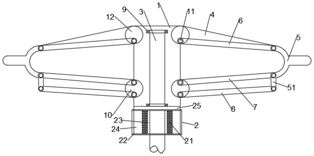
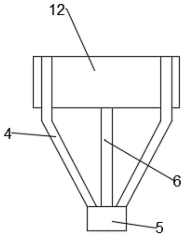
[0019] Such as figure 1 and figure 2 As shown, the present invention provides a wing drive mechanism of an aircraft, including a shaft sleeve rod 1, a central shaft rod 3 and a drive mechanism 2, and the central shaft rod 3 extends longitudinally through the drive rotation mechanism 2 to the sleeve rod 1 At the inner top, an action sleeve 25 is arranged between the shaft sleeve rod 1 and the excitation mechanism 2, and the top and bottom of the inner part of the shaft sleeve rod 3 are equipped with rolling bearings 9, and the rolling bearings 9 It is fixedly connected with the inside of the shaft sleeve rod 1, the top two ends of the shaft sleeve rod 1 are fixedly provided with a second hinge 12, the bottom outer wall of the shaft sleeve rod 1 is fixedly provided with a first hinge 10, and the second hinge 12 Rigid arm bars 4 are hinged at the left and right ends of the second hinge 12, the first piezoelectric bimorph 6 is hinged in the middle of the second hinge 12, and the...


PUM


Abstract

The invention discloses a wing driving mechanism of an aircraft, which comprises a shaft sleeve rod, a central shaft rod and an excitation mechanism, an action sleeve is arranged between the shaft sleeve rod and the excitation rotation mechanism, and the central shaft rod is located at the top of the inner part of the shaft sleeve rod and the bottom are fitted with rolling bearings, the top two ends of the shaft sleeve rod are fixedly provided with a second hinge, the bottom outer wall of the shaft sleeve rod is fixedly provided with a first hinge, the left and right ends of the second hinge are hinged with rigid arm rods, and the second hinge The first piezoelectric bimorph is hinged in the middle, the two rigid arms and the top of the first piezoelectric bimorph are jointly hinged with a wing rigid rod, and the bottom of the connecting wing rigid rod is connected with a secondary link section, and the secondary link section The top and the bottom are respectively hinged with the second piezoelectric bimorph and the third piezoelectric bimorph, and the other ends of the second piezoelectric bimorph and the third piezoelectric bimorph are hinged on the first hinge, through the two sets of piezoelectric The dual drive of the double chip and the drive mechanism, more powerful drive, and better controllability.

Description

technical field [0001] The invention relates to the technical field of aircraft, in particular to a wing driving mechanism of an aircraft. Background technique [0002] Micro air vehicle is a new research focus and direction in the field of international aviation. Researchers at home and abroad have developed various types of MAVs. According to the current research and development situation, according to the flight mode, they can be divided into: fixed-wing MAVs, rotary-wing MAVs, and flapping-wing MAVs. Compared with fixed-wing MAVs, rotor MAVs The biggest advantage of aircraft is that it can take off and land vertically and hover, which is more suitable for use in more complex environments. However, existing rotorcraft require motors or oil engines to drive the rotor to actively rotate, and the tail rotor is required to offset the impact of the rotor on the body. Torsion, resulting in complex structure, large mass and low aerodynamic efficiency. The flapping-wing micro-ai...

Claims


Application Information

Patent Timeline
Patent Type & Authority Patents(China)
IPC IPC(8): B64C33/02
CPCB64C33/02
Inventor 沈海锋李杨宇
Owner 沈海锋
Why Eureka
Try Eureka