
Fluidization feeding device for fluidized bed boiler

A fluidized bed boiler and feeding device technology, applied in the direction of incinerators, combustion methods, combustion types, etc., can solve the problems of flue gas or ash leakage, reduce boiler and feeding parts air leakage, etc., to reduce CO and other pollution Formation of substances, prevention of expansion and deformation, and improvement of economical efficiency

Pending Publication Date: 2018-04-13
HANGZHOU HAILU HEAVY IND +1
View PDF6 Cites 3 Cited by
  • Summary
  • Abstract
  • Description
  • Claims
  • Application Information

AI Technical Summary

Problems solved by technology

[0002] Due to the high moisture content of the waste in the existing fluidized bed waste incineration boiler furnace, there are common problems of waste blockage and poor feeding. Once the material is blocked in the feeding device, the feeding will not be carried out continuously. Seriously affect the safety, stability and continuous operation of the boiler and even the entire waste incineration generating set, and even cause a shutdown accident
In addition, the feeding device of the existing fluidized bed waste incineration boiler generally adopts an adiabatic structure, and there is no effective cooling measure for the feeding pipeline. Due to the influence of factors such as continuous high-temperature radiation from the furnace and the backflow of high-temperature flue gas inside the feeding pipeline, Severe expansion and deformation occurred, resulting in local cracking, so the sealing performance of the feeding pipeline could not be effectively guaranteed, causing problems such as air leakage, smoke leakage or ash leakage at the feeding part, which occurred from time to time and were difficult to eliminate, resulting in boiler operation. The environment is harsh and reduces the economics of boiler operation
In addition, the moisture in the domestic waste entering the furnace will not only reduce the economical efficiency of the boiler operation, but also have a very adverse effect on the generation of pollutants such as CO in the fluidized bed waste incineration boiler

Method used


Image

  • Fluidization feeding device for fluidized bed boiler
  • Fluidization feeding device for fluidized bed boiler

Examples


Embodiment Construction

[0014] In order to make the above objects, features and advantages of the present invention more comprehensible, the specific implementation manners of the present invention will be described in detail below in conjunction with the accompanying drawings.

[0015] Example.

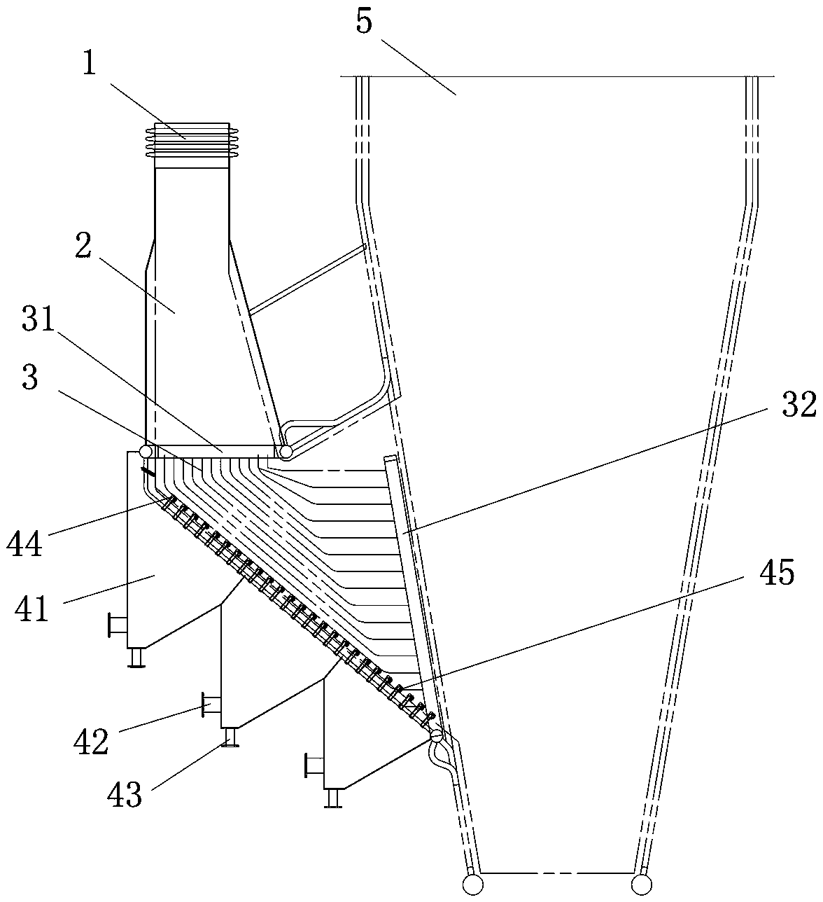
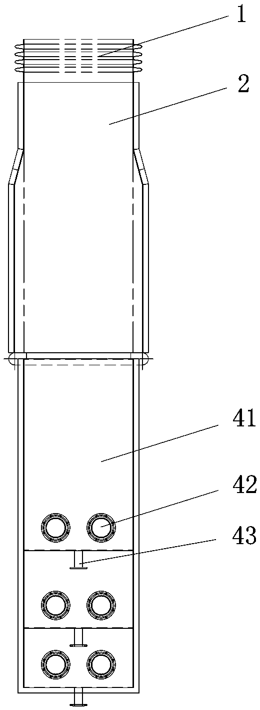
[0016] Such as Figure 1-2 As shown, this embodiment includes an expansion joint 1, a feeding material connecting tank 2, a feeding material chamber 3 and a fluidization device, wherein the inner walls of the feeding material connecting tank 2 and the feeding material chamber 3 are coated with refractory castables. Coating refractory castables on the inner walls of the feeding connecting tank 2 and the feeding chamber 3 can improve the heat resistance of the feeding connecting tank 2 and the feeding chamber 3, and extend the feeding connecting tank 2 and the feeding chamber 3 service life.

[0017] The upper end of the expansion joint 1 is connected with the drop pipe, and the lower end is connected with ...


PUM


Abstract

The invention belongs to the field of garbage incineration boilers and particularly relates to a fluidization feeding device for a fluidized bed boiler. The fluidization feeding device comprises an expansion joint, a feed connecting chute, a feed cavity and a fluidizing device. One end of the expansion joint is connected with a material falling pipe. The fluidizing device comprises a plurality offeed air bellows. The feed air bellows are sequentially fixed to the lower end of the feed cavity in a stepped mode. A membrane water-cooling wall is arranged outside each feed cavity. The feed cavityis provided with a feed port and a discharge port. The feed port is connected with the lower end of the feed connecting chute. The discharge port is connected with the boiler. A plurality of directional wind caps are arranged in the feed cavity and are sequentially fixed to the inner wall of the lower end of the feed cavity in a stepped mode. The lower ends of the directional wind caps are connected with the feed air bellows. The fluidization feeding device is scientific in structure and can make charged garbage fuel keep in a fluidized state and sufficiently receive high-temperature radiantheat in a boiler hearth so as to reduce the water content of the garbage fuel. Meanwhile, the fluidization feeding device is provided with a plurality of cooling facilities which can protect the fluidization feeding device against expansive deformation and cracks due to being superheated.

Description

technical field [0001] The invention belongs to the field of waste incineration boilers, and in particular relates to a fluidized feeding device for a fluidized bed boiler. Background technique [0002] Due to the high moisture content of the waste in the existing fluidized bed waste incineration boiler furnace, there are common problems of waste blockage and poor feeding. Once the material is blocked in the feeding device, the feeding will not be carried out continuously. Seriously affect the safety, stability and continuous operation of the boiler and even the entire waste incineration generating set, and even cause a shutdown accident. In addition, the feeding device of the existing fluidized bed waste incineration boiler generally adopts an adiabatic structure, and there is no effective cooling measure for the feeding pipeline. Due to the influence of factors such as continuous high-temperature radiation from the furnace and the backflow of high-temperature flue gas insi...

Claims


Application Information

Patent Timeline
Patent Type & Authority Applications(China)
IPC IPC(8): F23G5/30F23G5/44
CPCF23G5/30F23G5/444F23G2205/20
Inventor 韩新儿王武忠白红俊吴勇俊杨俊荣王忠
Owner HANGZHOU HAILU HEAVY IND
Learn More