Reinforced heat exchange type radiation convection cool-heat exchanger

A cold and heat exchanger, enhanced heat transfer technology, applied in household heating, heating methods, household heating, etc., can solve the problems of large air flow disturbance, low heat transfer coefficient, easy to produce blowing sensation, etc., to improve heat transfer effect of ability

Inactive Publication Date: 2018-04-13
DALIAN UNIV OF TECH
View PDF4 Cites 4 Cited by
  • Summary
  • Abstract
  • Description
  • Claims
  • Application Information

AI Technical Summary

Problems solved by technology

At present, in the field of building heating and air conditioning terminal equipment in my country, there are very few types of terminal equipment that can supply both cold and heat, and can also bear the humidity load while supplying cooling. The most common is the fan coil unit, but the fan coil unit relies on the unit The forced convection formed by a small centrifugal or cross-flow fan in the air circulation heats or cools the indoor air. Not only the air flow is disturbed, it is easy to produce a feeling of blowing, but the noise and fan energy consumption are relatively large; the other common one can be cooled, The end of both heat supply is the end of the ground (or ceiling) radiant panel, and for thi

Method used


Image

  • Reinforced heat exchange type radiation convection cool-heat exchanger
  • Reinforced heat exchange type radiation convection cool-heat exchanger
  • Reinforced heat exchange type radiation convection cool-heat exchanger

Examples


Embodiment Construction

[0016] The present invention will be further described below in conjunction with the accompanying drawings.

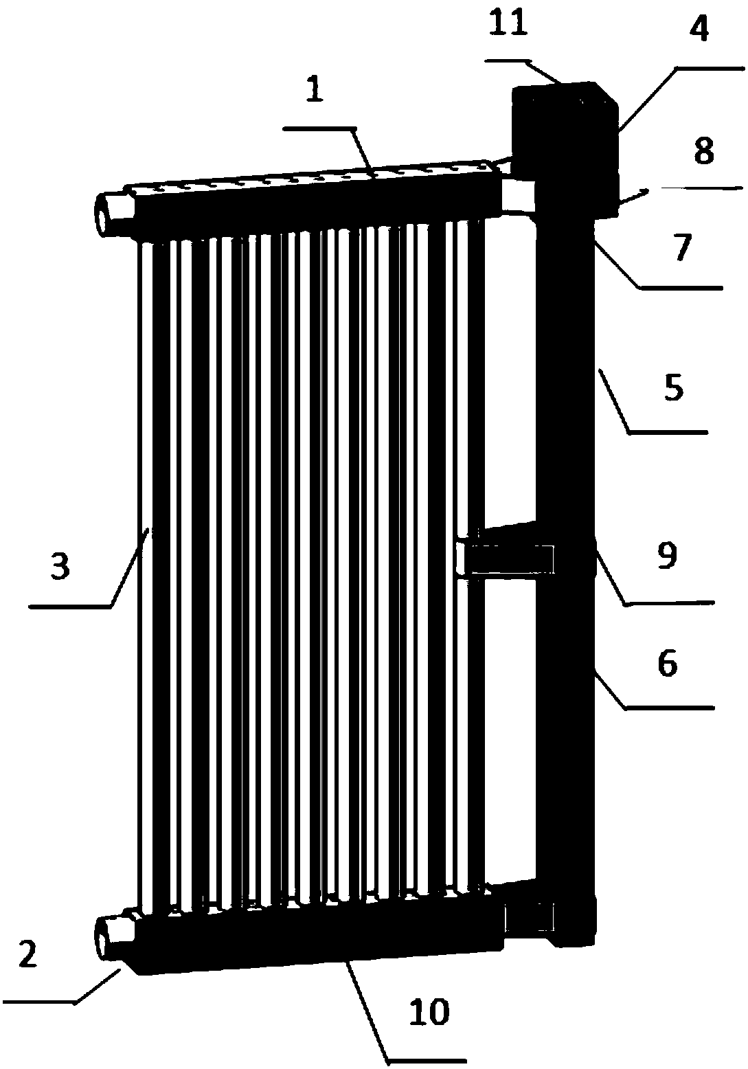
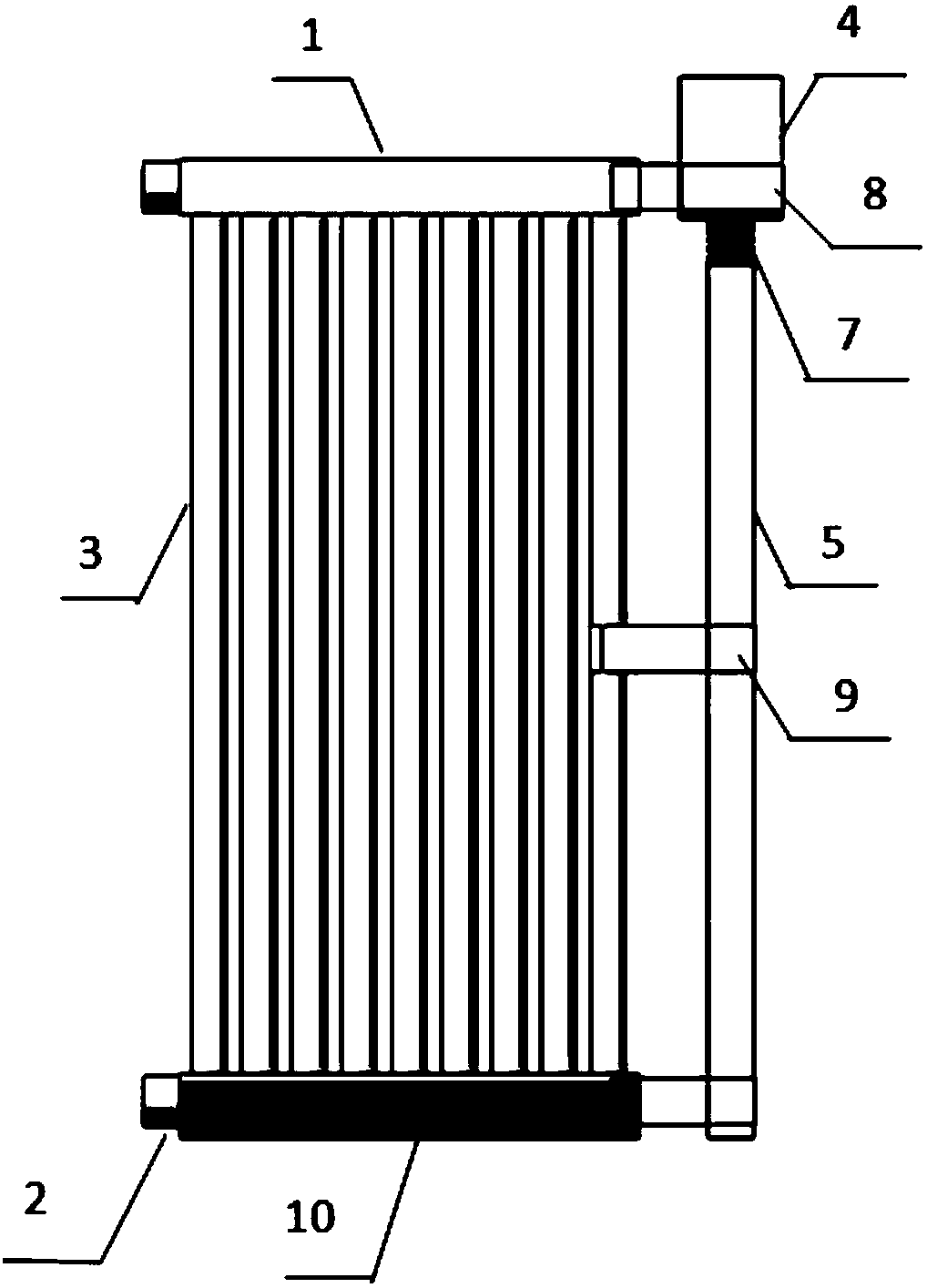
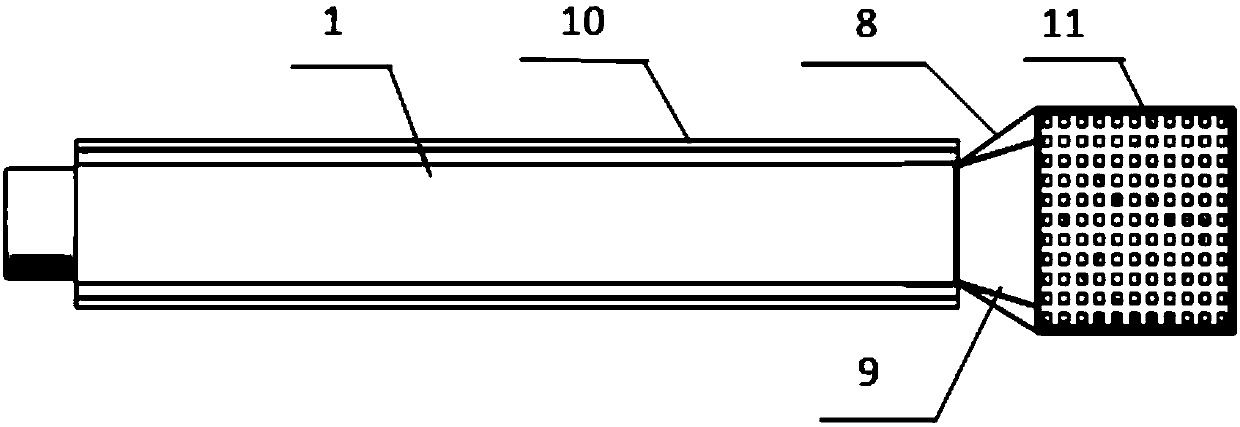
[0017] An enhanced heat exchange type radiation convection cold heat exchanger, mainly composed of the upper header 1 of the radiation convection cold heat exchanger, the lower header 2 of the radiation convection cold heat exchanger, and the heat exchange tube 3 of the radiation convection cold heat exchanger , small fan 4, vertical air supply pipe with side air supply port 5, side air supply port 6, soft connection between fan and vertical air pipe 7, fan welding steel plate 8, vertical air supply pipe welding steel plate 9, condensation water tank 10. The fan inlet steel wire mesh 11 is composed. The outer surfaces of the upper header 1 , the lower header 2 and all the radiation convection heat exchange tubes 3 are covered with a super-hydrophobic coating. The vertical air supply pipe 5 is provided with a rectangular or circular side air supply port 6 close to the ...


PUM

PropertyMeasurementUnit
Lengthaaaaaaaaaa

Abstract

The invention discloses a reinforced heat exchange type radiation convection cool-heat exchanger and belongs to the field of heating, ventilating and air conditioning system terminal devices. The reinforced heat exchange type radiation convection cool-heat exchanger comprises an upper collecting pipe, a lower collecting pipe, heat exchange pipes, a water condensing groove, a small-size fan, a vertical air supply pipe with side air supply openings, a flexible coupling, a welding steel plate of the fan, a welding steel plate of the vertical air supply pipe and fan inlet steel wire mesh. According to the reinforced heat exchange type radiation convection cool-heat exchanger, the winter heating and summer cooling capabilities of the device are remarkably enhanced in a manner that airflow turbulence outside a heat exchange pipe bank is increased. By means of the terminal device, the air output speed can be changed by adjusting gears of the fan under the circumstance of different indoor cooling and heating loads; furthermore, the heat exchange amount of the terminal device is adjusted; and the purpose that the indoor temperature is controlled is achieved. The gears of the fan are dividedinto three types, namely the high gear, the middle gear and the low gear; and by means of the water condensing groove in the lower portion of the cool-heat exchanger, condensed water, generated in the cooling process, on the surface of equipment is collected, and the indoor humidity load is borne. The reinforced heat exchange type radiation convection cool-heat exchanger is flexible to mount anduse; noise and consumption generated in the working process are low; and the heat comfort requirement of human bodies can be well met.

Description

technical field [0001] The invention belongs to the technical field of HVAC system terminal device design, and particularly relates to a technology that can be used to enhance the heat exchange effect of the HVAC terminal device. Background technique [0002] The development of the economy has made people put forward higher requirements for the indoor air environment of long-term living and working. The buildings in most areas such as the north of the Yellow River in my country not only have heating needs in winter, but also air conditioning and cooling needs in summer. The terminal equipment of the cooling and heating system is the last link to adjust the indoor temperature. Its main function is to exchange heat and moisture with the indoor environment to maintain the indoor air environment within the comfortable range of the human body. At present, in the field of building heating and air conditioning terminal equipment in my country, there are very few types of terminal e...

Claims


Application Information

Patent Timeline
IPC IPC(8): F24F13/22F24F13/30F24F13/24
CPCF24F13/222F24F13/24F24F13/30F24F2013/247
Inventor 舒海文姜珊张宏亮端木琳
Owner DALIAN UNIV OF TECH
Why Eureka
Try Eureka