
Permanent magnet linear motor

A permanent magnet linear motor and body technology, which is applied to electrical components, electromechanical devices, electric components, etc., can solve the problems of uneven cooling, waste, and increase of parts, so as to suppress the body temperature rise, improve the cooling effect, and increase the volume of refrigerant. Effect

Pending Publication Date: 2018-04-13
GUANGZHOU HAOZHI ELECTROMECHANICAL
View PDF0 Cites 0 Cited by
  • Summary
  • Abstract
  • Description
  • Claims
  • Application Information

AI Technical Summary

Problems solved by technology

[0003] However, these two commonly used methods have the following defects: the method of increasing the flow rate of the refrigerant has additional requirements for the external cooling pump, the pressure and flow of the refrigerant need to be increased, and the sealing pressure requirements of the motor itself have been greatly increased, which is prone to uneven cooling ; However, the solution of isolating the machine table from the primary components requires additional components, occupying the space of the machine tool and cooling flow, resulting in additional waste

Method used


Image

  • Permanent magnet linear motor
  • Permanent magnet linear motor
  • Permanent magnet linear motor

Examples


Embodiment Construction

[0025] Below, the present invention will be further described in conjunction with the accompanying drawings and specific implementation methods. It should be noted that, under the premise of not conflicting, the various embodiments described below or the technical features can be combined arbitrarily to form new embodiments. .

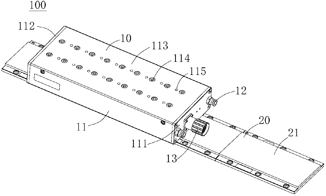
[0026] Such as figure 1 As shown, a permanent magnet linear motor 100 includes a primary assembly 10 and a secondary assembly 20 .

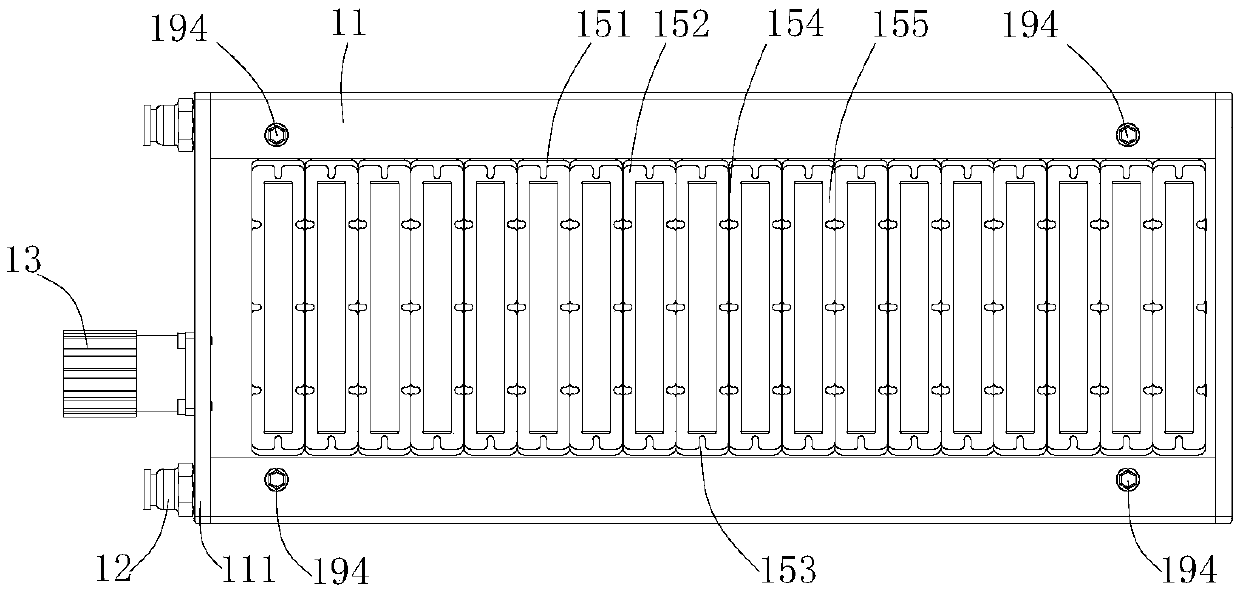
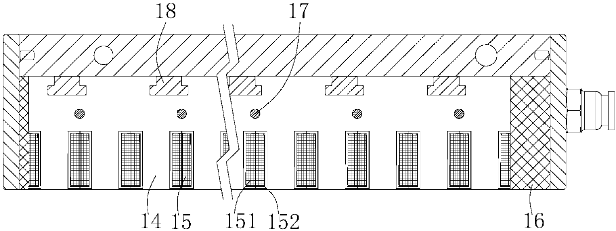
[0027] Such as Figure 2-6 As shown, the primary assembly 10 includes a body 11 , a cooling connector 12 , a power connector 13 , a primary core 14 , a coil winding 15 , a primary potting compound 16 , a connecting rod 17 , a connecting block 18 and a cooling channel 19 .

[0028] The body 11 includes a front fender 111 , a rear fender 112 and a top mounting plate 113 . The front protective plate 111 and the rear protective plate 112 are screwed to the two ends of the main body of the body 11 to form a mold cavity. A ...


PUM


Abstract

The invention discloses a permanent magnet linear motor. The permanent magnet linear motor comprises a primary assembly; the primary assembly comprises a machine body, primary iron cores, a pluralityof coil windings, cooling connectors and cooling flow channels; the multiple coil windings are in mutual connection and fixed on the primary iron cores; the primary iron cores are fixedly connected with the machine body and positioned in the machine body; the cooling connectors are fixed at one end of the machine body; the outer walls of the cooling flow channels are tightly attached to the primary iron cores and the multiple coil windings; the cooling flow channels comprise top cooling flow channels and side surface cooling flow channels; one ends of the side surface cooling flow channels areconnected with the top cooling flow channels while the other ends are connected with the cooling connectors; and the hole diameters of the cooling flow channels are larger than that of the cooling connectors. According to the permanent magnet linear motor, the cooling flow channels are tightly attached to the primary iron cores and the coil windings to directly cool a heat source, so that a goodeffect is realized; the hole diameters of the cooling flow channels are larger than that of the cooling connectors, so that the refrigerant amount in the cooling flow channels is increased, and machine body temperature rise is suppressed effectively; and in addition, the side surface cooling flow channels are matched with the top cooling flow channels, so that the volume of the refrigerant storedin the machine body is further enlarged.

Description

technical field [0001] The invention relates to a mechanical motor, in particular to a permanent magnet linear motor. Background technique [0002] Permanent magnet linear motors have the dual characteristics of permanent magnet motors and linear motors. They have the characteristics of large thrust, high speed, and small size. They are the first choice for high-speed and high-precision linear feed systems. At present, permanent magnet linear motors are more and more widely used in industrial machinery such as machining centers, PCB drilling machines, forming machines, electrical discharge machines, and gantry systems. In order to solve the problem of poor thermal shock performance, there are usually the following methods: increase the refrigerant flow rate, use a larger refrigerant flow rate to quickly take away the heat from the motor; isolate the machine from the primary component, use other cooling devices to separate the primary and The machine is isolated to prevent t...

Claims


Application Information

Patent Timeline
IPC IPC(8): H02K41/03H02K9/19H02K3/24
CPCH02K3/24H02K9/19H02K41/031
Inventor 郭治汤秀清
Owner GUANGZHOU HAOZHI ELECTROMECHANICAL
Learn More