
Mammary gland positioning part and mammary gland positioning apparatus

A positioning component and positioning device technology, applied in the field of medical equipment, can solve problems such as inability to concentrate, low comfort, and inability to reduce heart and lung volume, and achieve the effect of convenient operation and simple structure

Pending Publication Date: 2018-04-17
朱远湖
View PDF2 Cites 5 Cited by
  • Summary
  • Abstract
  • Description
  • Claims
  • Application Information

AI Technical Summary

Problems solved by technology

However, the prone position also has many disadvantages: 1. The prone position causes the patient’s breasts to be unable to be fully presented in the field of vision of the medical staff, which is not convenient for repeated positioning, and cannot ensure the high precision of radiotherapy; 2. Compared with the supine position, the prone position The comfort is low, which increases the range and probability of involuntary movement of the patient's body; 3. The prone position is more suitable for patients with larger breasts. Due to ethnic reasons, Chinese breasts are generally smaller
However, the supine position will make the breast tissue cover the chest wall and cannot be concentrated. The traditional supine position does not take any measures to keep the tumor area away from the heart and lungs, resulting in the inability to reduce the irradiated volume of the heart and lungs, which limits the radiotherapy effect of breast cancer

Method used


Image

  • Mammary gland positioning part and mammary gland positioning apparatus
  • Mammary gland positioning part and mammary gland positioning apparatus
  • Mammary gland positioning part and mammary gland positioning apparatus

Examples


Embodiment Construction

[0055] The present invention will be described in further detail below in conjunction with the accompanying drawings.

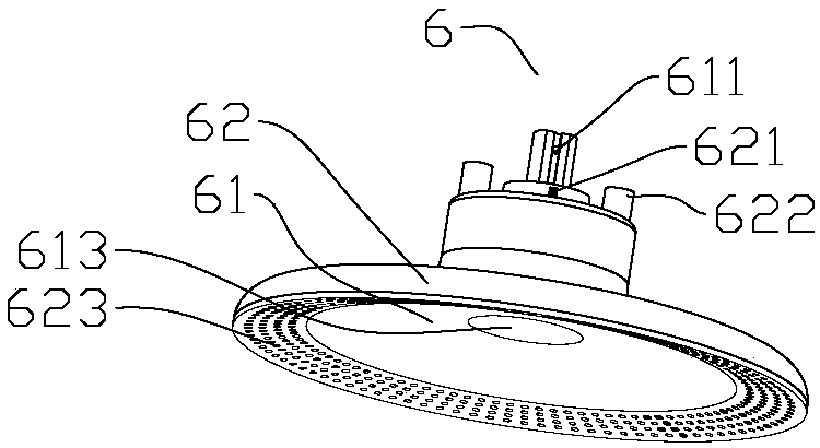
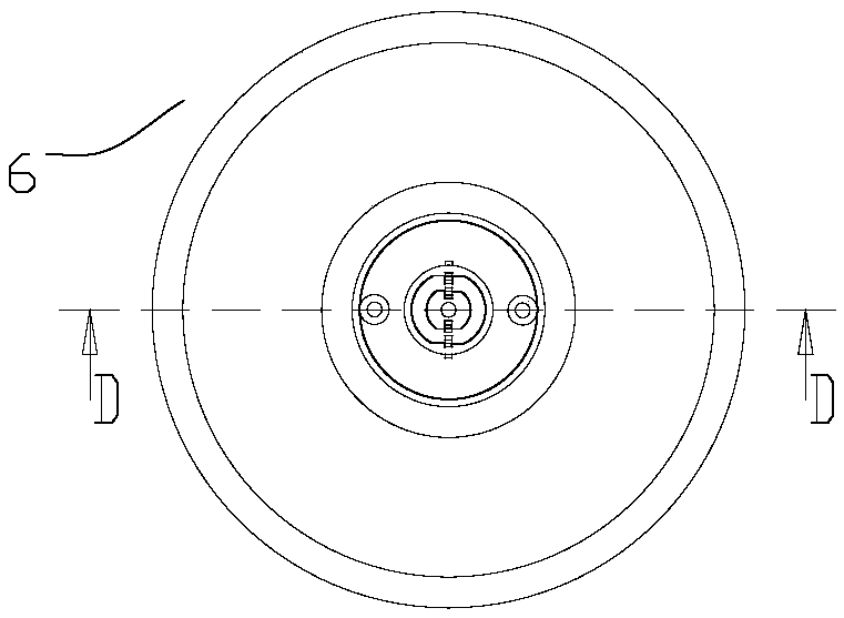
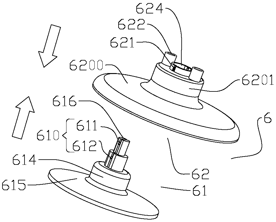
[0056] Figure 1 to Figure 5 A mammary gland positioning member 6 according to an embodiment of the present invention is schematically shown. Such as figure 1 , Figure 3 to Figure 5As shown, the mammary gland positioning component 6 includes a base body 62, and the base body 62 is provided with an air suction structure, and the air suction structure is used to suck up the breast, and at the same time, the mammary gland in the breast is sucked up together; the base body 62 is also integrally formed with a cavity 625, The cavity 625 is located on the side of the base body 62 facing the mammary gland (such as Figure 5 The lower surface of the base body 62 shown), the cavity 625 is used to fix the suctioned mammary gland.

[0057] During mammary gland radiotherapy, when using the breast positioning part 6 to locate the patient's breast, the patient can adop...


PUM


Abstract

The invention discloses a mammary gland positioning part and a mammary gland positioning apparatus. The mammary gland positioning part comprises a base body provided with a suction structure for sucking a mammary gland up; and a cavity for fixing the sucked mammary gland is formed at one side, facing the mammary gland, of the base body. Because of the suction structure arranged at the base body ofthe mammary gland positioning part, the mammary gland positioning part is fixed at a breast firmly by the suction effect of the suction structure. The base body has a simple structure and the operation becomes convenient. Meanwhile, the cavity for fixing the sucked mammary gland is arranged at the base body, so that the mammary gland is fixed stably. The mammary gland positioning part is used forsucking up the mammary gland of the patient, so that the lesion mammary gland can be kept away from the heart and lung while the patient does not need to lie prostrate. Therefore, the injuries of thenormal heart and lung tissues by the rays during the radiotherapy can be reduced and the sequel of radiotherapy is reduced.

Description

technical field [0001] The invention relates to a medical device, in particular to a mammary gland positioning component and a mammary gland positioning device. Background technique [0002] Radiation therapy is the principle that when ray irradiates cells, it can destroy the chromosomes of cells, thereby inhibiting and killing cells. The purpose of inhibiting and killing cancer cells is achieved by irradiating cancer cells. [0003] Radiation therapy generally includes the following main processes: positioning, target area delineation, plan design, plan verification, and treatment (usually multiple treatments). During the treatment process, radiation is used to irradiate the affected part of the patient, and the cancer cells are irradiated by radiation to inhibit and kill the cancer cells and achieve the purpose of curing the patient. However, since the principle of ray inhibiting and killing cancer cells is achieved by destroying the chromosomes of the cells, when the ray...

Claims


Application Information

Patent Timeline
IPC IPC(8): A61N5/10
CPCA61N5/10A61N2005/1097
Inventor 朱远湖张红志
Owner 朱远湖
Learn More