Efficient separation type biomass particle combustor

A biomass particle separation technology, which is applied in the direction of combustion equipment, solid fuel combustion, lighting and heating equipment, etc., can solve the problem of low combustion efficiency of separated and clean biomass particle burners, and achieve simple and effective screening of ash. The effect of high transportation efficiency and simple structure

Inactive Publication Date: 2018-04-17
SICHUAN ZHONGYONG PHARMA CO LTD
View PDF0 Cites 1 Cited by
  • Summary
  • Abstract
  • Description
  • Claims
  • Application Information

AI Technical Summary

Problems solved by technology

[0003] The purpose of the present invention is to solve the problem that it is difficult for the decoking device in the prior art to separate the ash and small pieces of coked matter, which leads to the low combustion efficiency of the biomass pellet burner. This application provides a high-efficiency separation type Biomass pellet burner

Method used


Image

  • Efficient separation type biomass particle combustor
  • Efficient separation type biomass particle combustor
  • Efficient separation type biomass particle combustor

Examples


Embodiment 1

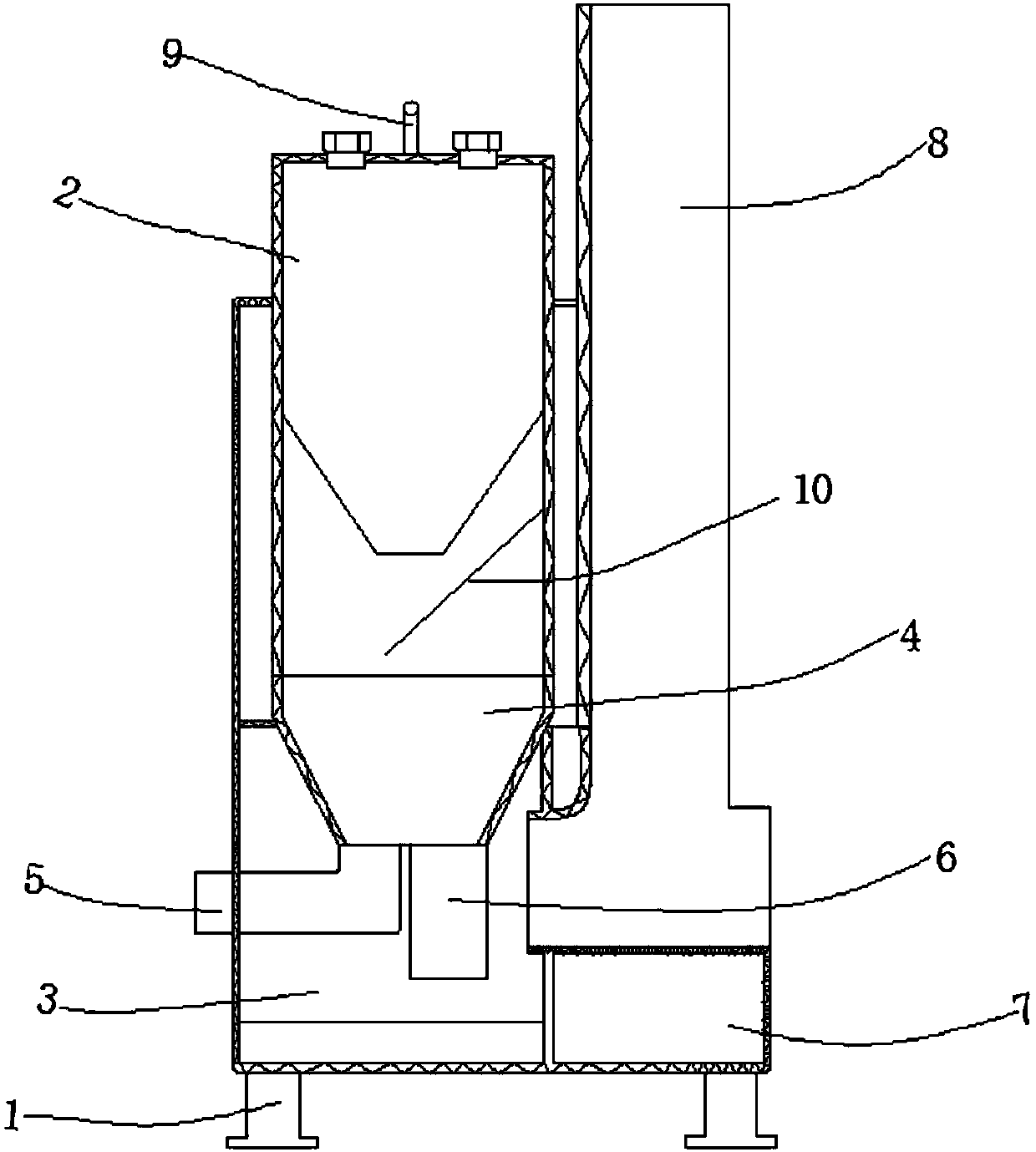
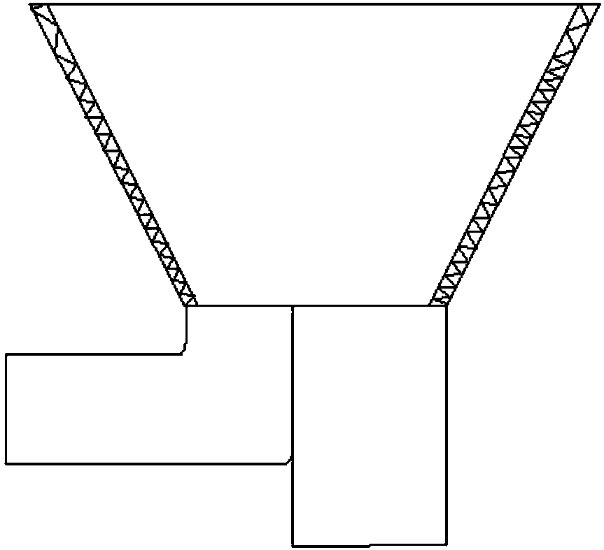
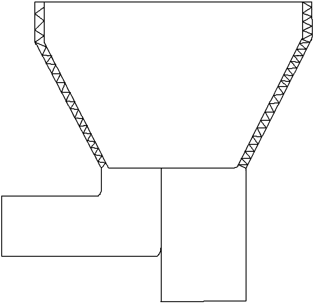
[0026] This embodiment provides a high-efficiency separated biomass pellet burner, including: a frame 1, a first combustion chamber 2 arranged on the frame 1, a second combustion chamber 3, and a first combustion chamber 2 and a second combustion chamber for discharging The flue 8 of the flue gas of the second combustion chamber 3, the external equipment 7 that fits the flue 8 and the second combustion chamber 3 are characterized in that it also includes a collection device 10 arranged in the first combustion chamber 2 and The distributing mechanism 4 used for the separation of ash and coking substances is arranged between the first combustion chamber 2 and the second combustion chamber 3. The distributing mechanism 4 includes an ash outlet 5 and a coking substance outlet 6. The coking substance outlet 6 is connected to the second coking substance outlet. The two combustion chambers 3 are connected, and the burned material of the first combustion chamber 2 first enters the side...

Embodiment 2

[0029] On the basis of Embodiment 1, the ash screening area 4-5 is provided with ash holes through which the ash goes out, and the coked matter in the first combustion chamber 2 enters the second combustion chamber 3 through the coked matter discharge area 4-6.

[0030] This embodiment provides a simple ash screening area 4-5 structure, but here as long as the ash after the combustion of the first combustion chamber 2 can be separated, the diameter of the ash is generally much smaller than the diameter of the coked material. Therefore, this embodiment uses this rule to directly set the gray matter screening area 4-5 into a network structure, wherein the diameter of the gray matter hole is kept similar to the diameter of the gray matter.

Embodiment 3

[0032] On the basis of embodiment two, a pusher for pushing the coking material in the gray matter screening area 4-5 to the coking material output area 4-6 is provided between the gray matter screening area 4-5 and the coking material discharge area 4-6. Material organization;

[0033] When the pushing mechanism is not provided, the coking material in the gray matter screening area 4-5 will be pushed to the coking material discharge area 4-6 under the extrusion of the burned material in the first combustion chamber 2, but in this way, the biomass The efficiency of the particle burner is low, and it is faster to push the coking material in the ash screening area 4-5 to the coking material discharge area 4-6 by using the pushing mechanism;

[0034] Since the pushing mechanism includes a connecting rod, a rake connected to the connecting rod, and a drive mechanism for driving the connecting rod, the components in it are all conventional components, and this application does not ...


PUM


Abstract

The invention discloses an efficient separation type biomass particle combustor, and aims at solving the problem that in a decoking device in the prior art, thorough separation of ash and small cokedsubstances is very hard, and consequently, the combustion efficiency of a biomass particle combustor is low. According to the efficient separation type biomass particle combustor, a material separating mechanism is arranged between a first combustion chamber and a second combustion chamber, materials obtained after combustion in the first combustion chamber enter a material collecting device, thematerials obtained after combustion enter an ash screening area through the material collecting device firstly, and after ash screening, the left materials are conveyed into the second combustion chamber through a coked substance area under extrusion of the upper materials; and in other words, through the efficient separation type biomass particle combustor, the ash is screened firstly, the left coked materials are subjected to second-time sufficient combustion in the second combustion chamber, sufficient retaining of the coked substances is achieved, and the material combustion efficiency isimproved. The efficient separation type biomass particle combustor is applicable to the field of biomass particle combustors.

Description

technical field [0001] The invention relates to the field of biomass particle burners, in particular to a high-efficiency separation type biomass particle burner. Background technique [0002] The biomass pellet burner is powered by burning biomass pellets. It is widely used in boilers, die-casting machines, industrial furnaces, incinerators, smelting furnaces, kitchen equipment, drying equipment, food drying equipment, ironing equipment, paint baking equipment, Various thermal energy industries such as road construction machinery and equipment, industrial annealing furnaces and asphalt heating equipment. A biomass pellet burner usually consists of a first combustion chamber, a second combustion chamber, a fan, an oxygen supply device, a decoking device, and a driving device. The char-like substances are put into the second combustion chamber to continue to burn fully. In the first combustion chamber, in addition to the unburned coke-like substances, there are also some ash...

Claims


Application Information

Patent Timeline
IPC IPC(8): F23B10/02F23J1/00
CPCF23B10/02F23J1/00
Inventor 刘金成刘浩云蔡帮明秦会
Owner SICHUAN ZHONGYONG PHARMA CO LTD
Why Eureka
Try Eureka