MEMS thermal acoustic particle sensor

A sensor and particle technology, applied in instruments, measuring propagation velocity, measuring ultrasonic/sonic/infrasonic waves, etc., can solve the problems of large thermal noise heating, low cut-off frequency, and poor high-frequency characteristics, so as to reduce self-noise and influence The effect of weakening and improving high-frequency characteristics

Active Publication Date: 2018-04-17
PEKING UNIV
View PDF10 Cites 15 Cited by
  • Summary
  • Abstract
  • Description
  • Claims
  • Application Information

AI Technical Summary

Problems solved by technology

[0005] The self-noise is large, because the two suspension beams of a pair of wire groups are heated, the thermal noise generated is larger than that of a single suspension beam;
[0006] The high-fr...

Method used


Image

  • MEMS thermal acoustic particle sensor
  • MEMS thermal acoustic particle sensor
  • MEMS thermal acoustic particle sensor

Examples


Embodiment Construction

[0031] In order to make the above objects, features and advantages of the present invention more obvious and understandable, the present invention will be further described in detail below in conjunction with the accompanying drawings and specific embodiments.

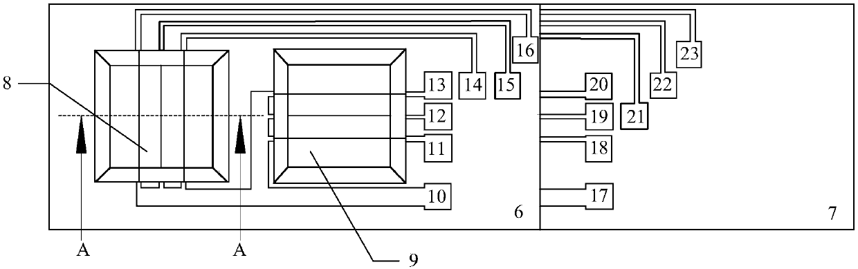
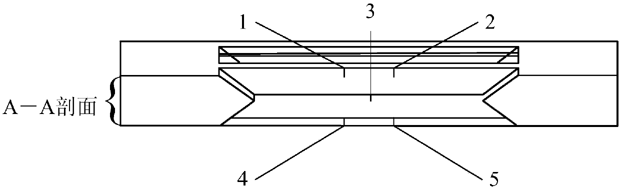
[0032] The sensor designed in the present invention is a three-layer beam structure, and its top view is as follows: figure 1 As shown, the upper pole plate 6 and the lower pole plate 7 are stacked. Two left and right windows (8 and 9) are made on the two plates, and each layer has corresponding beam leads and pads (such as pads 10 to 23 visible in the top view), which is convenient for detecting circuit measurement data and data processing. There are 5 beams in the measuring unit of the sensor. The main factor to be considered in the selection of the middle layer beam process plan is the processing method of the middle heating beam. It is difficult to directly process the three-layer beam structure. The present inven...


PUM


Abstract

The invention discloses an MEMS thermal acoustic particle sensor and relates to the field of microelectronic machining, and in particular relates to a design method for the MEMS thermal acoustic particle sensor. Currently, based on a principle of a two-wire flowmeter, conventional MEMS thermal acoustic particle sensors have large self-noise and poor high-frequency characteristics. To solve this problem, the present invention provides a MEMS three-wire thermal acoustic particle sensor structure that can be applied to sound source positioning. The sensor has a three-layer cantilever structure which is formed by bonding upper and lower polar plates and consists of two right and left measuring units having orthogonal planes. Two temperature sensing resistance cantilever beams are arranged on each of two upper and lower layers of each measuring unit, and a heating resistance cantilever beam from an upper plate or a lower plate is arranged on a middle layer. Four cantilever beams on the upper and lower layer form a rectangle, and the cantilever beam on the middle layer is located at the center of the rectangle. Processing steps include a step of making three cantilever beams on each of two front and back surfaces of the upper and lower polar plates of each measuring unit, a step of removing excessive cantilever beams in the upper and lower polar plates, and a step of bonding the upper and lower polar plates together.

Description

technical field [0001] The invention relates to the field of microelectronic machining, in particular to a design method of a MEMS thermal acoustic particle sensor. Background technique [0002] Acoustic vector sensor technology is one of the most promising research directions in the field of underwater acoustic technology in the 21st century in my country, and it is also widely used in industry and life. In daily life, vector sensors can be used for sound positioning, such as vehicle fault detection, life detection, etc.; in the field of underwater acoustics, they can be used for underwater acoustic signal detection, underwater investigation, etc. Acoustic vector includes two parts: acoustic particle velocity and sound pressure. Among them, the detection method of sound pressure is relatively mature, but the detection of acoustic particle velocity is a major difficulty. [0003] Traditional acoustic particle sensors are not based on microelectronics technology, but use ind...

Claims


Application Information

Patent Timeline
IPC IPC(8): G01H5/00
CPCG01H5/00
Inventor 罗中良李哲高成臣金玉丰郝一龙
Owner PEKING UNIV
Why Eureka
Try Eureka