
Installation method for dust removal device for distribution box

The technology of a dust removal device and installation method, which is applied in the direction of switchgear, electrical components, etc., can solve the problems of time-consuming and laborious, inconvenient operation, short circuit of vacuum cleaner dust collection line, etc., and achieve the effect of simple installation process, realization of cleaning and convenient installation

Active Publication Date: 2019-04-30
宁波南顿电力科技有限公司
View PDF5 Cites 0 Cited by
  • Summary
  • Abstract
  • Description
  • Claims
  • Application Information

AI Technical Summary

Problems solved by technology

However, because the distribution box is generally installed on the side of the road, dust is easily deposited on the circuit board in the distribution box.
However, due to the large number of lines in the distribution box, it is easy to cause short circuit and other faults due to contact with the line when using a vacuum cleaner to clean the dust.
However, if you use a normal fan to blow the dust, you can’t blow all the dust out of the distribution box, and some dust will be blown into the distribution box, and the dust removal effect is not good.
Moreover, manual dust removal is basically used now, which is inconvenient and time-consuming and laborious to operate.

Method used


Image

  • Installation method for dust removal device for distribution box
  • Installation method for dust removal device for distribution box

Examples


Embodiment

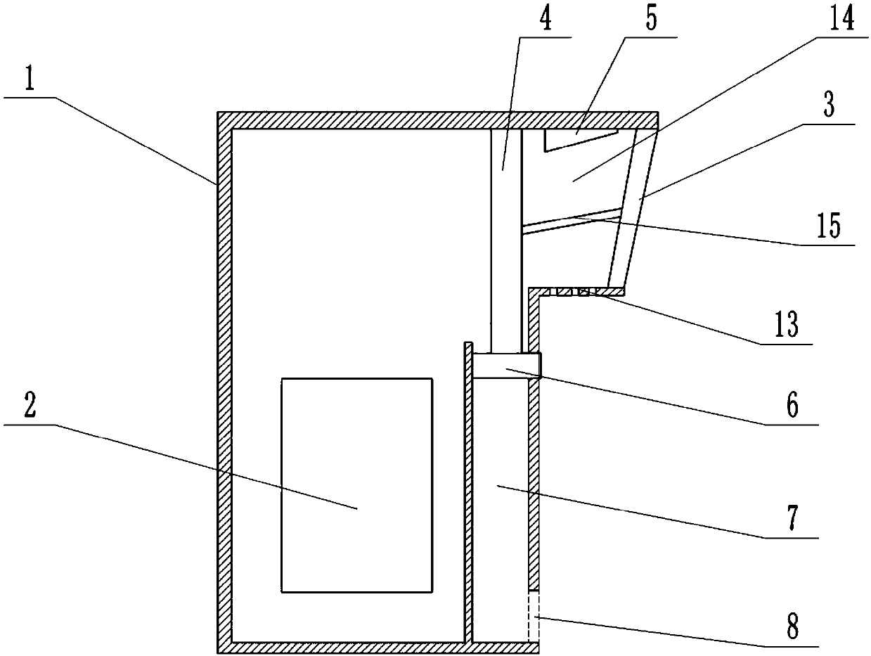
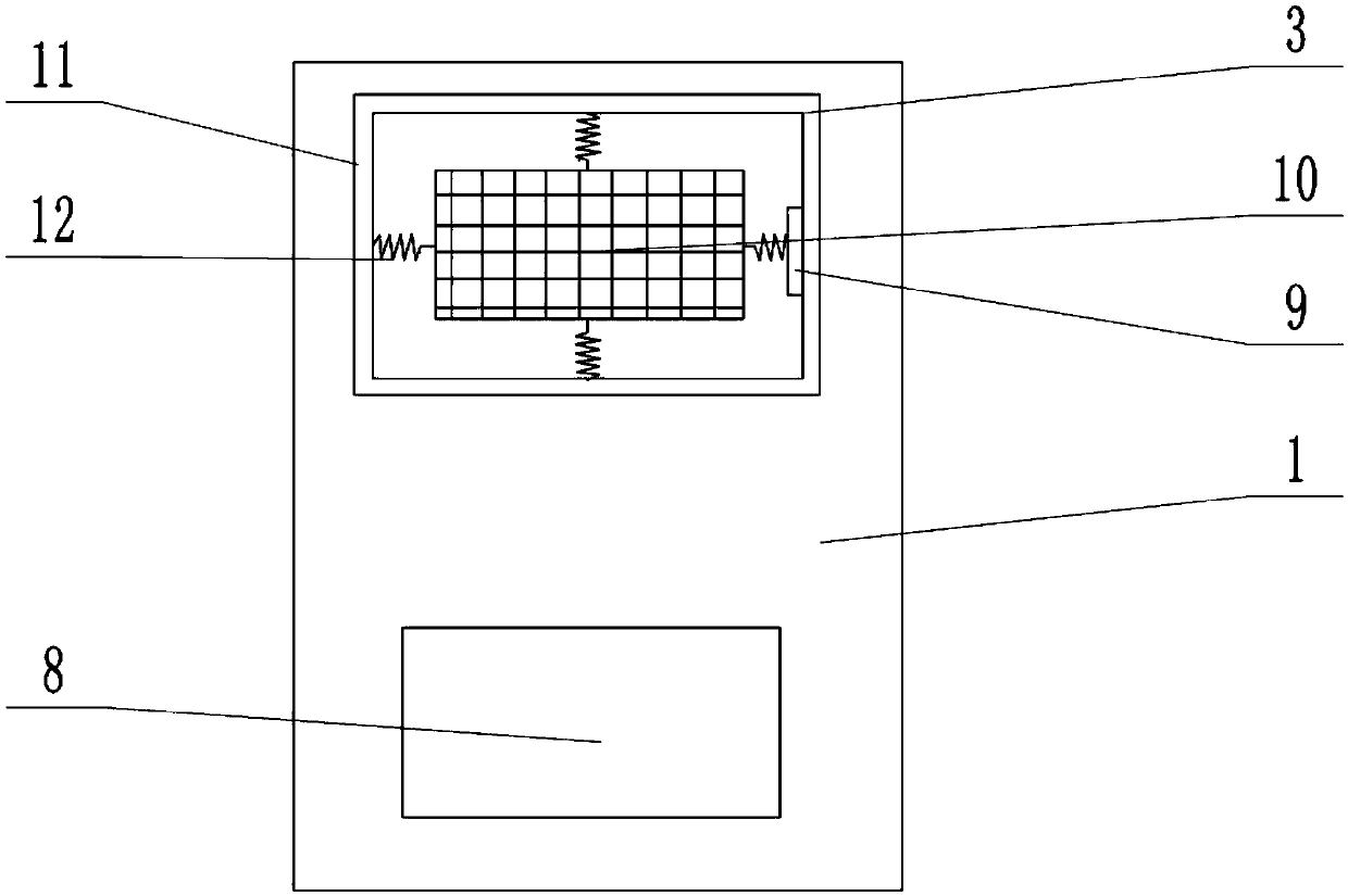
[0032] Such as figure 1 with 2 As shown, the dust removal device of the distribution box 1 used in this embodiment includes the blowing pipe 14 that is used to extend outwards on the distribution box 1 and communicate with the blowing port 3, and the insulation that is arranged on the blowing pipe 14 of the distribution box 1 Frame 11; a shakeable metal mesh 10 and an electrostatic generator connected to the metal mesh 10 are arranged in the insulating frame 11, and the upper part of the metal mesh 10 is inclined to the outside of the distribution box 1; the insulating frame 11 has four side walls, each A spring 12 is hinged between each side wall and the metal mesh 10; the right side wall of the insulating frame 11 is provided with an electromagnet 9 for absorbing the metal mesh 10; the electromagnet 9 is connected to the same electric circuit with the electrostatic generator, and the electromagnet 9 electric connections have the microcontroller that is used for regularly co...


PUM


Abstract

The invention belongs to the electrical control field, and specifically discloses a mounting method used for a dust removal apparatus of a power distribution box. The mounting method comprises the following steps of 1, setting a spring on the inner wall of an insulating frame matched with an air blowing port of the power distribution box; 2, connecting a metal net in the insulating frame through the spring; 3, setting an electromagnet on one side wall of the inner wall of the insulating frame; 4, mounting the insulating frame in the air blowing port of the power distribution box, and mountinga static generator connected with a metal net circuit on the power distribution box; 5, enabling the electromagnet and the static generator to be connected in the same electric loop; and 6, mounting aswitch used for controlling the electromagnet and the static generator to be started or closed on the power distribution box. Compared with the prior art, the mounting process is simple and the mounting is convenient; by virtue of the mounted dust removal apparatus of the power distribution box, dust in the power distribution box can be cleaned without needing manpower operation; and by virtue ofthe spring, metal net shaking is realized, and dust on the metal net can be cleaned, so that the metal net adsorbed with dust also does not need manpower cleaning.

Description

technical field [0001] The application of the present invention belongs to the field of electrical control, and specifically discloses an installation method for a dust removal device for a distribution box. Background technique [0002] A distribution box is an electrical device used to distribute electrical energy. A circuit board is installed in the distribution box. In order to dissipate heat for the circuit board in the distribution box, a blower port is generally provided on the side wall of the distribution box. However, because the distribution box is generally installed on the side of the road, dust is easily deposited on the circuit board in the distribution box. However, due to the large number of lines in the distribution box, it is easy to cause short circuit and other faults due to touching the lines with a vacuum cleaner. However, if ordinary fans are used to blow the dust, all the dust cannot be blown out of the distribution box, and some dust will be blown...

Claims


Application Information

Patent Timeline
Patent Type & Authority Patents(China)
IPC IPC(8): H02B3/00
CPCH02B3/00
Inventor 邱红光
Owner 宁波南顿电力科技有限公司
Learn More