
Light source having a controllable spectrum

A light source and control device technology, applied in spectrometry/spectrophotometry/monochromator, using diffraction elements to generate spectra, optics, etc., can solve the problem of insufficient spectral purity, adverse effects of spectral resolution, spectral power density, and light source Large distance and other problems, to improve the effect of spectral filtering

Pending Publication Date: 2018-04-17
仪器系统有限公司
View PDF3 Cites 0 Cited by
  • Summary
  • Abstract
  • Description
  • Claims
  • Application Information

AI Technical Summary

Problems solved by technology

However, it is disadvantageous that the distance between the light sources arranged next to each other is thus relatively large
This adversely affects achievable spectral resolution and achievable spectral power density
Moreover, it was found that the achievable spectral purity of the generated light is still insufficient for various applications

Method used


Image

  • Light source having a controllable spectrum

Examples


Embodiment Construction

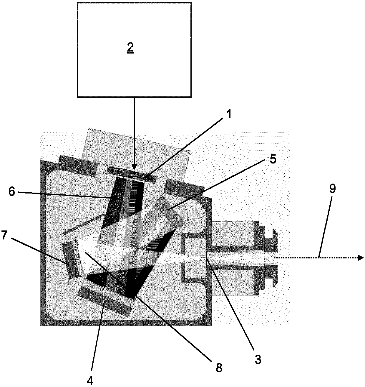
[0028] The device shown comprises an array 1 of LEDs as light sources, which are arranged next to one another in the plane of the illustration, the LEDs in any case partially differing from one another with respect to their emission spectra. Colored LEDs are used in the blue and red spectral ranges. White LEDs are used in the green spectral range. It is also possible to use only white LEDs that cover the entire desired spectral range and have a high spectral density.

[0029] The LED array 1 is driven by an electronic control unit 2 .

[0030] A superposition optics unit is provided which superimposes the light emitted by the LED array 1 in the outlet 3 . The superposition optical unit includes a first concave mirror 4 , and the LED array 1 is located in the focal plane of the first concave mirror 4 . A grating 5 is provided onto which the first concave mirror 4 reflects the light 6 emitted by the LED array 1 . The second concave mirror 7 reflects the light 8 diffracted at...


PUM


Abstract

The invention relates to an apparatus for generating light, comprising a plurality of light sources (1), a control device (2), which drives the light sources (1), and a superimposition optical unit, which superimposes the light emitted by the light sources (1) in an exit opening (3). It is an object of the invention to provide an apparatus which is improved compared with the prior art. For this purpose, the invention proposes that the superimposition optical unit comprises a first concave mirror (4), in the focal plane of which the light sources (1) are situated, an optical grating (5), onto which the first concave mirror (4) reflects the light (6) emitted by the light sources (1), and a second concave mirror (7), which reflects the light (8) diffracted at the optical grating (5) onto theexit opening (3) situated at the focus of the second concave mirror (7).

Description

technical field [0001] The invention relates to a device for emitting light, comprising: [0002] - multiple light sources, [0003] - a control device, which drives the light source, [0004] - A superposition optical unit superimposing the light emitted by the light source in the outlet. Background technique [0005] Such a device is known for example from US 6,075,595. The previously known device comprises a plurality of light sources (LEDs) arranged linearly alongside each other in a one-dimensional array, in particular with a predetermined distance between the individual light sources. A separate dispersed concave mirror is used as the superposition optical unit, which is fixed and focuses the light from the source on the outlet in a wavelength-dependent manner according to its position within the linear array. The light source is driven by an electronic control unit. For this purpose, the control device generates a pulse signal for each individual light source, so...

Claims


Application Information

Patent Timeline
IPC IPC(8): G01J3/02G01J3/10G01J3/18G02B19/00G02B27/10G02B27/42
CPCG01J3/0297G01J3/18G02B27/1086G02B27/425G01J2003/104G01J2003/1286G01J3/0218G01J3/10G02B19/0066G02B17/0804G02B5/10F21V7/06F21V7/00
Inventor F·弗兰克M·埃斯特曼C·卡佩尔F·舍韦R·黑林A·温克勒C·M·R·格里夫斯
Owner 仪器系统有限公司
Learn More