Rope deterioration detection device and elevator apparatus having rope deterioration detection device

A technology of deterioration detection and rope, which is applied in the direction of measuring devices, transportation and packaging, and testing the strength of materials by applying a stable bending force, which can solve the problems of large measurement deviation, increased error, and difficult inspection

Active Publication Date: 2020-03-20
MITSUBISHI ELECTRIC CORP
View PDF13 Cites 0 Cited by
  • Summary
  • Abstract
  • Description
  • Claims
  • Application Information

AI Technical Summary

Problems solved by technology

However, in this method, the unevenness of the surface of the wire rope leads to large measurement deviations, and if the operator is not skilled enough, the error will further increase, so it is difficult to perform inspections with high accuracy.

Method used


Image

  • Rope deterioration detection device and elevator apparatus having rope deterioration detection device
  • Rope deterioration detection device and elevator apparatus having rope deterioration detection device
  • Rope deterioration detection device and elevator apparatus having rope deterioration detection device

Examples


Embodiment approach 1

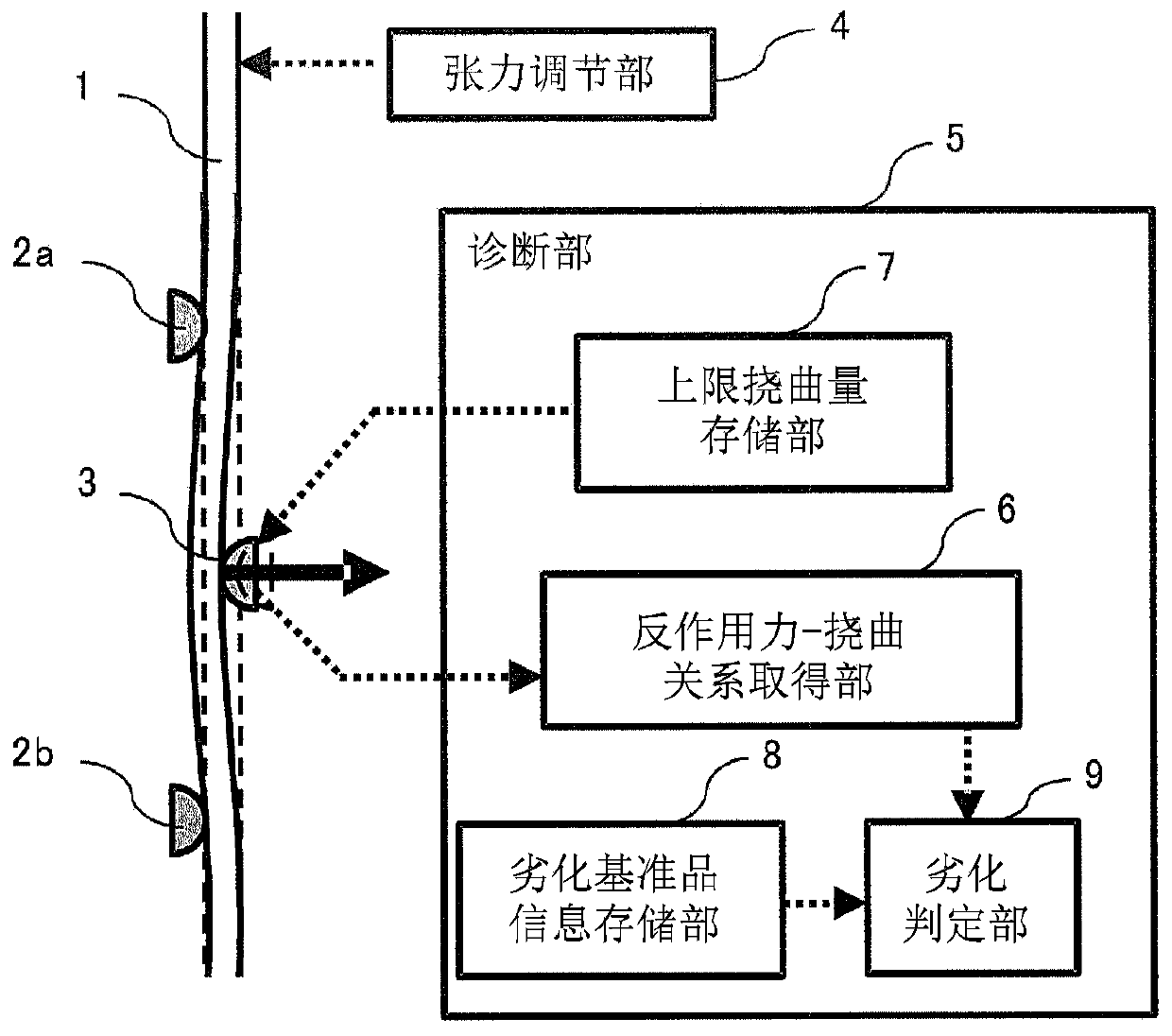
[0037] figure 1 It is a block diagram of the wire rope deterioration detection apparatus in Embodiment 1 of this invention. The cord 1 is provided with a support portion 2 a and a support portion 2 b for supporting the cord at both ends of a range to be diagnosed.

[0038] On the other hand, a bend imparting portion 3 is provided at an intermediate point between the support portion 2a and the support portion 2b, and the bend imparting portion 3 imparts a bend to the rope 1 supported by the support portion 2a and the support portion 2b. In addition, the tension adjustment unit 4 is provided at an arbitrary position outside the range of the diagnostic object. exist figure 1 In the example, the case where the tension adjustment part 4 is provided above the support part 2a is shown.

[0039] In addition, a diagnostic unit 5 is provided that receives the reaction force and the amount of deflection generated in the bending imparting unit 3 as inputs. The diagnostic unit 5 is con...

Embodiment approach 2

[0077] In Embodiment 1 above, the case where the height information of the normalized hysteresis loop is used as the deterioration diagnosis index has been described. On the other hand, in the second embodiment, a case will be described in which the area of ​​the normalized hysteresis loop is used as the deterioration diagnosis index instead of the height information of the normalized hysteresis loop.

[0078] Figure 11 It is a graph showing the difference in the area of ​​the normalized hysteresis loop in Embodiment 2 of the present invention. exist Figure 11 In , the hysteresis loop of the reaction force-deflection relationship of the intact rope is shown by a dotted line, and the hysteresis loop of the reaction force-deflection relationship of the deteriorated rope is shown by a solid line.

[0079] Such as Figure 11 As shown, in the deterioration diagnosis of the second embodiment, the area of ​​the normalized hysteresis loop of the deterioration reference product is...

Embodiment approach 3

[0082] In the foregoing Embodiments 1 and 2, the case where the height or area of ​​the normalized hysteresis loop is used as the deterioration diagnosis index has been described. On the other hand, in this third embodiment, a certain amount of deflection X within the range of the bending portion when a load is used for the determination will be described. 0 to replace the case of the hysteresis loop.

[0083] as deflection X 0 , for example, the intersection of straight lines before and after the bent portion can be used. Figure 12 It is a graph showing the relationship between the inflection point and the upper limit deflection amount X in the reaction force-deflection relationship in Embodiment 3 of the present invention. exist Figure 12 In , the reaction force-deflection relationship of the intact rope is shown by a dotted line, and the reaction force-deflection relationship of the deteriorated rope is shown by a solid line.

[0084] Such as Figure 12 As shown, sin...


PUM


Abstract

The rope degradation detection device of the present invention has: a pair of supporting parts, its support ropes to bend the rope; bending to the department, which is bent to the rope supported by a pair of supporting parts;The reaction force obtained the department, and its bending force was given to the reaction force of the bending state by the bending department; the scratching department, the quantity of the bending state given by the bending department;The relationship between the reaction force obtained by the force and the deflection of the force and the deflection amount is calculated to calculate the determination parameter, and determine the degradation state of the rope.

Description

technical field [0001] The present invention relates to a rope deterioration detection device and an elevator device having the rope deterioration detection device, which detects a rope deterioration state up to a stage before a core wire breaks. Background technique [0002] When a steel wire rope with a structure in which strands twisted with a core wire are further twisted around the core is used continuously for a long period of time, deterioration progresses from both the inside and outside of the rope and eventually breaks. Therefore, when using a wire rope, it is necessary to regularly check the state of the inside and outside of the rope, and replace it before it reaches a fracture. [0003] As a method of inspecting a steel wire rope, first, visual inspection or diameter measurement, which are manual methods, is usually carried out. The former visual inspection of the appearance is a method in which an operator visually inspects the surface for abrasion, core wire ...

Claims


Application Information

Patent Timeline
Patent Type & Authority Patents(China)
IPC IPC(8): G01N3/20B66B5/02B66B7/12
CPCG01N3/20B66B7/1215G01N2203/028
Inventor 黑川弘海渡边诚治近藤力雄野口豊弘
Owner MITSUBISHI ELECTRIC CORP
Why Eureka
Try Eureka