Adaptive optical scanning laser fundus imaging system and imaging method based on automatic positioning and focusing of pupils

An adaptive optics and automatic positioning technology, applied in the field of medical equipment, can solve the problems of inability to locate and focus in real time, time-consuming operation, and micro-movement of the head. short effect

Pending Publication Date: 2018-04-20
THE EYE HOSPITAL OF WENZHOU MEDICAL UNIV
View PDF9 Cites 6 Cited by
  • Summary
  • Abstract
  • Description
  • Claims
  • Application Information

AI Technical Summary

Problems solved by technology

[0003] At present, ophthalmic examination equipment such as slit lamps, fundus cameras, optical coherence tomography scanners, and confocal laser scanners basically use the joystick to manually move the imaging system as a whole to achieve manual positioning and focusing of the pupils of the eyes. Personnel operation, inability to locate and focus in real time, and time-consuming operation, etc.
In addition, although it has been reported that the automatic positioning function can be achieved by moving the entire imaging device, the imaging system of the adaptive optics scanning laser fundus imaging system has a complex structure and a bulky volume, and it is difficult to achieve automatic and precise movement as a whole; or use jaw rests to move, Due to the movement of the head, it is easy to cause the relative slight movement of the head, and it is also difficult to ensure accurate positioning

Method used


Image

  • Adaptive optical scanning laser fundus imaging system and imaging method based on automatic positioning and focusing of pupils
  • Adaptive optical scanning laser fundus imaging system and imaging method based on automatic positioning and focusing of pupils
  • Adaptive optical scanning laser fundus imaging system and imaging method based on automatic positioning and focusing of pupils

Examples


Embodiment Construction

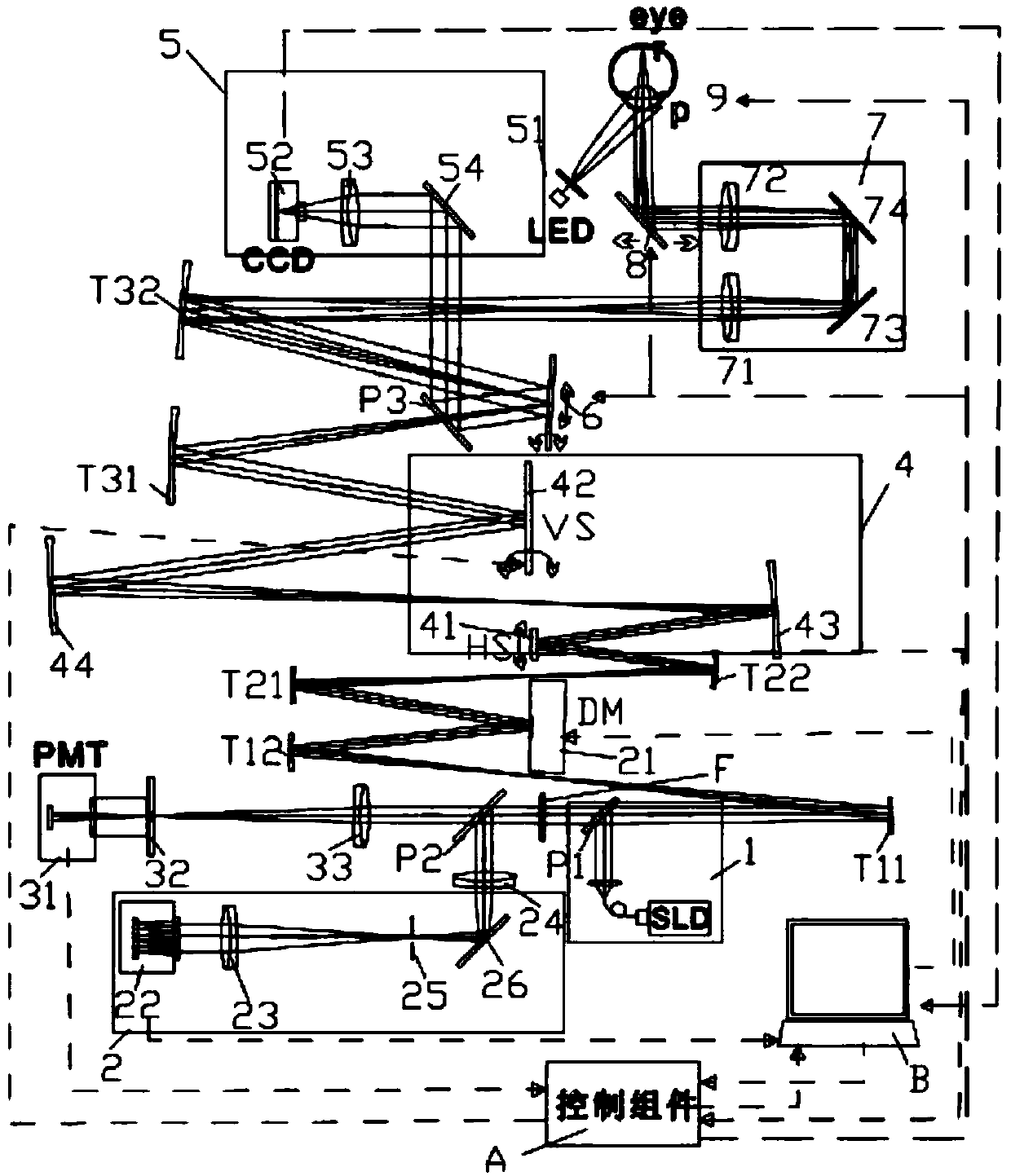
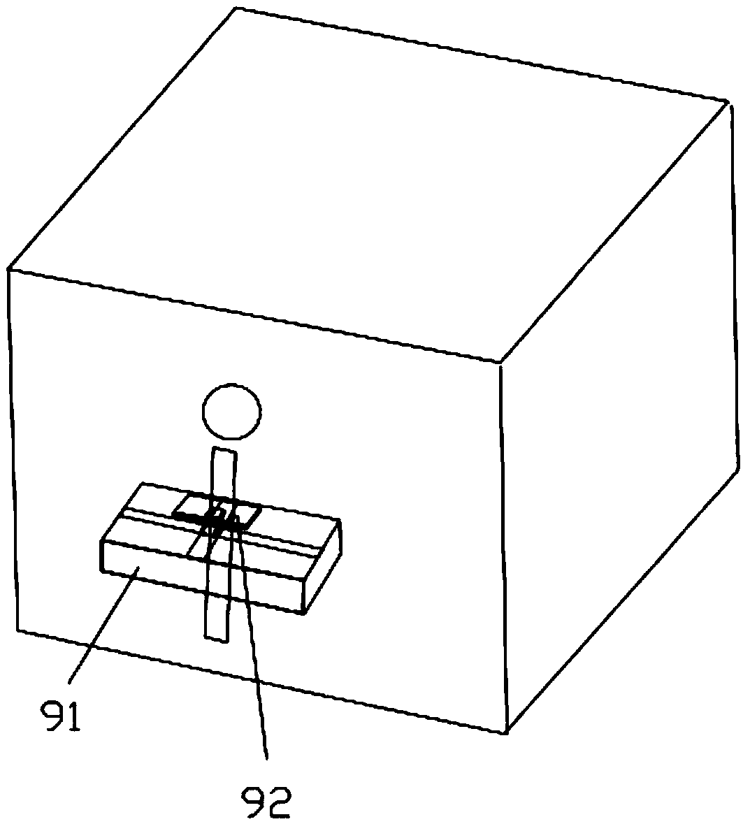
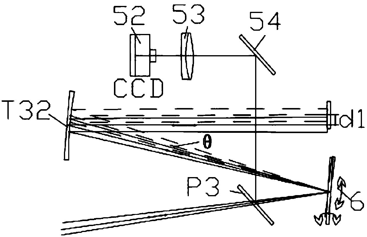
[0030] Combine now figure 1 , figure 2 , image 3 , Figure 4 The present invention is further described:

[0031]The adaptive optics scanning laser fundus imaging system based on pupil automatic positioning and focusing of the present invention includes an imaging light source assembly 1, an aberration correction assembly 21, an aberration detection assembly 2, an imaging detection assembly 3, a scanning optical path assembly 4, and a compensation mirror assembly 7 , pupil imaging assembly 5, pupil focusing assembly 8, pupil positioning assembly 6, chin rest moving assembly 9, control assembly A, computer B, respectively through spherical reflection type telescope T (T11 and T12, T21 and T22) between each above-mentioned assembly , T31 and T32) or optical coupler P (P1, P2, P3), the low coherent light emitted from the imaging light source assembly 1 passes through the aberration correction assembly 21, the scanning optical path assembly 4, the pupil positioning assembly 6...


PUM


Abstract

The invention discloses an adaptive optical scanning laser fundus imaging system and imaging method based on automatic positioning and focusing of pupils. The imaging system comprises an imaging lightsource component, an aberration detection component, an imaging detection component, a scanning light path component, a compensating mirror component, a pupil imaging component, a pupil focusing component, a pupil positioning component, a jaw support moving component, a control component and a computer, and the components are connected together through telescopes or light ray couplers. The imaging system is ingenious and unique in design, the head of a shot person leans on a jaw support, pupils are automatically positioned and focused by the aid of a combined mode of crude adjustment of the jaw support and fine adjustment of the imaging component according to existing positions of the pupils, and fundus images can be rapidly shot. According to the system, automatic fundus high-resolutionimaging can be achieved, the system has the advantages that the system is simple to operate, the pupil are positioned and focused in real time, operating consumption time is short and the like, operation of detectors is facilitated, and the system is suitable for large-scale popularization and application.

Description

technical field [0001] The invention relates to the field of medical equipment, in particular to an adaptive optical scanning laser fundus imaging system based on pupil automatic positioning and focusing and an imaging method thereof. Background technique [0002] The retina of the human eye is a human tissue with a complex structure. It is a microstructure organization. Many diseases of the human eye itself and systemic diseases of the whole body (such as glaucoma, diabetes, hypertension, etc.) can be reflected on the retina of the fundus. Many ophthalmology departments Diseases are accompanied by fundus changes, such as age-related macular degeneration, diabetic retinopathy, and intraocular tumors. Therefore, high-resolution imaging at the scale of tumors, blood vessels, and even cells in living human eyes has become an important research field in the field of retinal microscopic pathology. hotspot. At the same time, since the adaptive optics scanning laser fundus imaging...

Claims


Application Information

Patent Timeline
Patent Type & Authority Applications(China)
IPC IPC(8): A61B3/12A61B3/15
CPCA61B3/12A61B3/152
Inventor 江慧绿厉以宇李超宏廖娜陈浩连燕陈思韵
Owner THE EYE HOSPITAL OF WENZHOU MEDICAL UNIV
Why Eureka
Try Eureka