
Efficient cement paste manufacturing device preventing cement paste from splashing

A technology for making a device and cement slurry, which is applied to cement mixing devices, clay preparation devices, unloading devices, etc., can solve the problem that it is difficult to keep clean and tidy when preparing cement slurry.

Inactive Publication Date: 2018-04-20
邹祥茂
View PDF6 Cites 1 Cited by
  • Summary
  • Abstract
  • Description
  • Claims
  • Application Information

AI Technical Summary

Problems solved by technology

[0005] In order to overcome the disadvantage that it is difficult to keep clean and tidy when preparing grout in the prior art, the technical problem to be solved by the present invention is to provide a clean and tidy grout mixing device for making grout for home decoration

Method used


Image

  • Efficient cement paste manufacturing device preventing cement paste from splashing
  • Efficient cement paste manufacturing device preventing cement paste from splashing
  • Efficient cement paste manufacturing device preventing cement paste from splashing

Examples


Embodiment 1

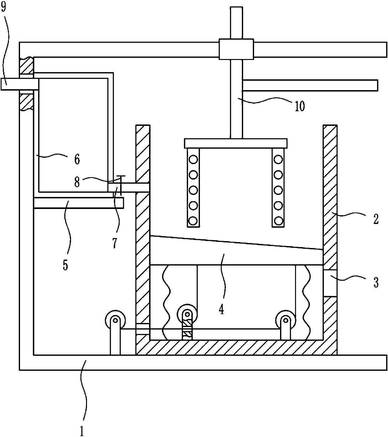
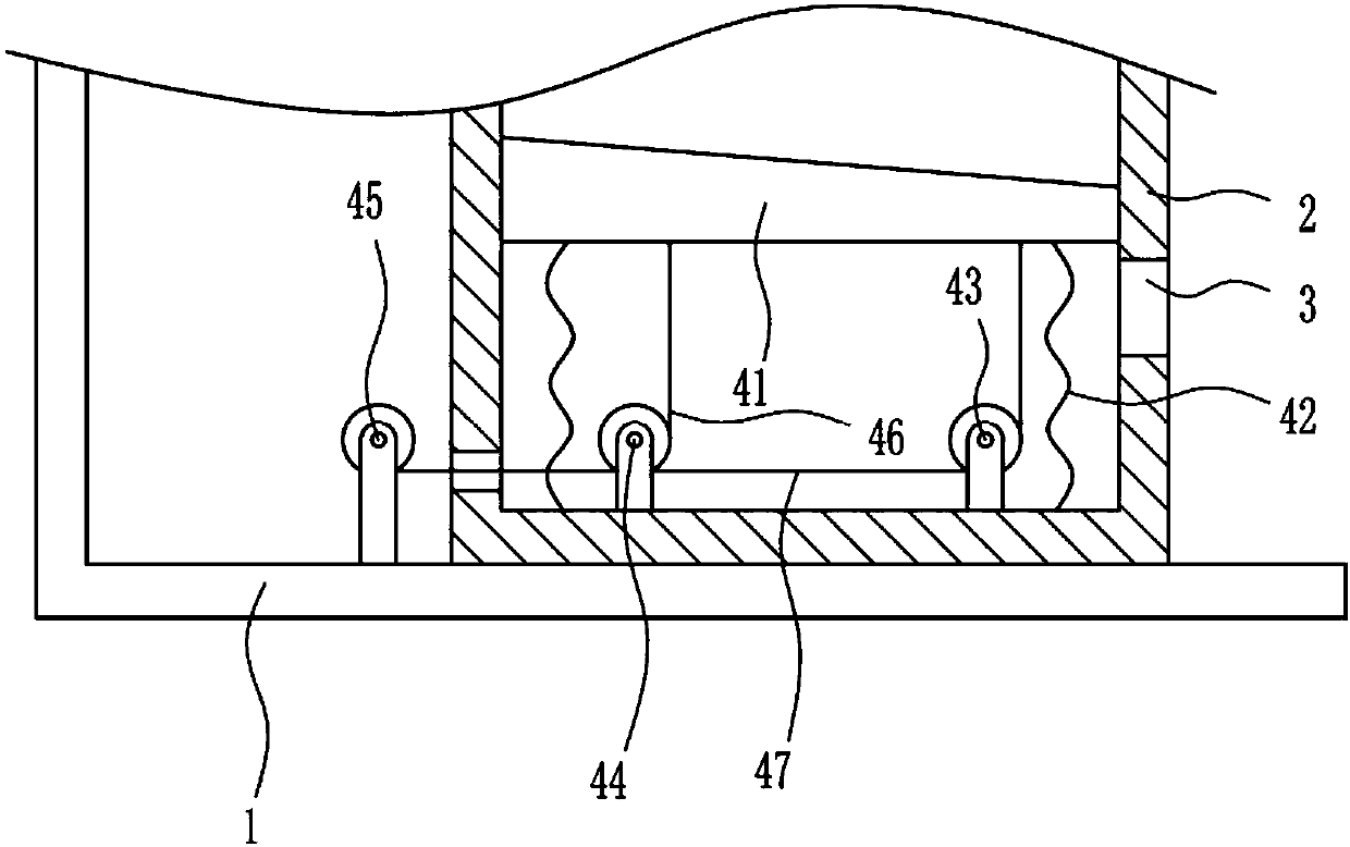
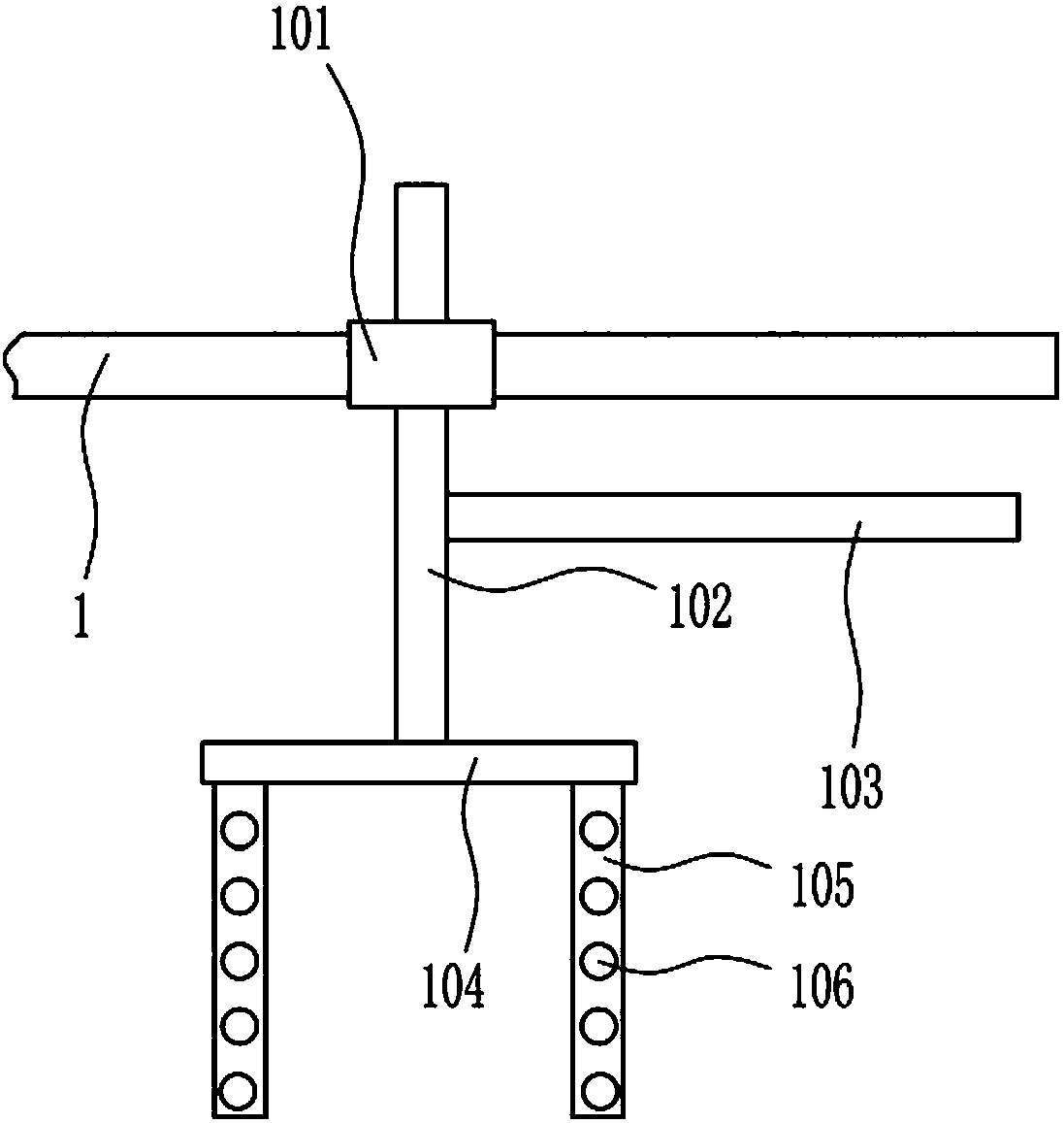
[0036] An efficient grout making device that prevents grout from splashing, such as Figure 1-5 As shown, it includes a mounting frame 1, a frame body 2, a lifting device 4, a placement plate 5, a water tank 6, a water outlet pipe 7, a valve 8, a water inlet pipe 9 and a stirring device 10, and a frame body is provided on the right side of the bottom of the mounting frame 1 2. There is a first through hole 3 in the lower part of the right wall of the frame body 2, a lifting device 4 is provided in the lower part of the frame body 2, a placement plate 5 is provided in the middle of the left wall of the installation frame 1, and a water tank 6 is placed on the top of the placement plate 5, and the water tank 6. The lower part of the right wall is provided with a water outlet pipe 7, and a valve 8 is arranged on the water outlet pipe 7. The water outlet pipe 7 is connected with the upper part of the left wall of the frame body 2. The upper part of the left wall of the water tank 6...

Embodiment 2

[0038] An efficient grout making device that prevents grout from splashing, such as Figure 1-5 As shown, it includes a mounting frame 1, a frame body 2, a lifting device 4, a placement plate 5, a water tank 6, a water outlet pipe 7, a valve 8, a water inlet pipe 9 and a stirring device 10, and a frame body is provided on the right side of the bottom of the mounting frame 1 2. There is a first through hole 3 in the lower part of the right wall of the frame body 2, a lifting device 4 is provided in the lower part of the frame body 2, a placement plate 5 is provided in the middle of the left wall of the installation frame 1, and a water tank 6 is placed on the top of the placement plate 5, and the water tank 6. The lower part of the right wall is provided with a water outlet pipe 7, and a valve 8 is arranged on the water outlet pipe 7. The water outlet pipe 7 is connected with the upper part of the left wall of the frame body 2. The upper part of the left wall of the water tank 6...

Embodiment 3

[0041] An efficient grout making device that prevents grout from splashing, such as Figure 1-5 As shown, it includes a mounting frame 1, a frame body 2, a lifting device 4, a placement plate 5, a water tank 6, a water outlet pipe 7, a valve 8, a water inlet pipe 9 and a stirring device 10, and a frame body is provided on the right side of the bottom of the mounting frame 1 2. There is a first through hole 3 in the lower part of the right wall of the frame body 2, a lifting device 4 is provided in the lower part of the frame body 2, a placement plate 5 is provided in the middle of the left wall of the installation frame 1, and a water tank 6 is placed on the top of the placement plate 5, and the water tank 6. The lower part of the right wall is provided with a water outlet pipe 7, and a valve 8 is arranged on the water outlet pipe 7. The water outlet pipe 7 is connected with the upper part of the left wall of the frame body 2. The upper part of the left wall of the water tank 6...


PUM


Abstract

The invention relates to preparation equipment, in particular to an efficient cement paste manufacturing device preventing cement paste from splashing. According to the technical problems to be solved, the cement paste preparation equipment for household building prepares cement cleanly and neatly. To solve the technical problems, the efficient cement paste manufacturing device preventing the cement paste from splashing comprises an installing frame, a frame body, a lifting device, a storing plate, a water tank, a water output pipe, a valve and the like. The frame body is arranged on the rightside of the inner bottom of the installing frame. A first through hole is formed in the lower portion of the right wall of the frame body. The lifting device is arranged on the inner lower portion ofthe frame body. The storing plate is arranged on the middle portion of the inner left wall of the installing frame. The water tank is arranged on the top of the storing plate. The water output pipe is arranged on the lower portion of the right wall of the water tank. The water output pipe is provided with the valve and connected with the upper portion of the left wall of the frame body. Accordingto the cement paste manufacturing device, a second through hole is formed in a stirring rod, the contact area of cement and water is enlarged, and the cement preparation speed is increased by means of cooperation of a first baffle and the water output pipe.

Description

technical field [0001] The invention relates to a blending equipment, in particular to a high-efficiency cement slurry production device which prevents the cement slurry from splashing. Background technique [0002] Cement, powdery hydraulic inorganic gelling material. Add water and stir to form cement slurry, which can be hardened in air or better hardened in water, and can firmly bond sand, stone and other materials together. In the early years the mixture of lime and volcanic ash is very similar to cement, use it to glue concrete which made of crushed stone. After hardening, the cement not only has high strength, but also can resist the erosion of fresh water or salt water. For a long time, as an important cementing material, it is widely used in civil engineering, water conservancy, national defense and other projects. However, in the existing cement slurry preparation equipment, the clothes of the operators are often difficult to keep clean, and are easily splashed by...

Claims


Application Information

Patent Timeline
Patent Type & Authority Applications(China)
IPC IPC(8): B28C5/16B28C7/12B28C7/16
CPCB28C5/16B28C7/12B28C7/16
Inventor 不公告发明人
Owner 邹祥茂
Learn More