Novel hydraulic servo-motor system and adopted control method
A control method and technology of oil motor, applied in the direction of engine components, machines/engines, mechanical equipment, etc., to achieve the effect of strong versatility and low cost
- Summary
- Abstract
- Description
- Claims
- Application Information
AI Technical Summary
Problems solved by technology
Method used
Image

Examples
Embodiment 1
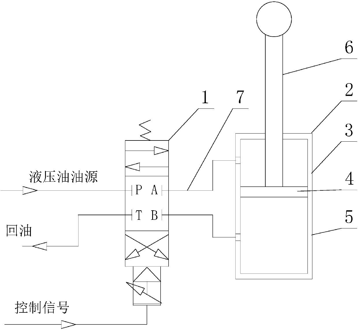
[0037] Such as figure 1As shown, this embodiment provides a specific implementation of a novel oil motor system, which includes a hydraulic control valve 1 and an oil motor 2;
[0038] The oil motor 2 is only composed of a cylinder 3, a piston 4 and a piston rod 6, the piston 4 is arranged in the cylinder 3, and the piston 4 divides the inner space of the cylinder 3 into two cavities 5, the The piston rod 6 is fixed on the piston 4;
[0039] It also includes two oil holes arranged on the cylinder body 3, and one of the oil holes communicates with one of the cavities 5, and the other oil hole communicates with the other cavity 5;
[0040] The hydraulic control valve 1 has at least two control oil ports, and the two oil holes are respectively connected to different control oil ports of the hydraulic control valve 1 through separate oil pipes 7, and the hydraulic oil flow direction of the two control oil ports can be switched .
[0041] Although the two oil motors 2 in the pri...
Embodiment 2
[0051] The present embodiment is further limited on the basis of embodiment 1, as figure 1 As shown, as a specific implementation of the hydraulic control valve 1, the hydraulic control valve 1 is an electro-hydraulic servo valve. Since the current steam turbine control system generally adopts the digital electro-hydraulic control system (DEH), the opening of the oil motor 2 is controlled through the electro-hydraulic servo valve. The direct oil return has been canceled, from the original control of only one oil circuit pressure to the simultaneous control of two oil circuit pressures, it seems that an additional oil circuit needs to be controlled, but in fact, the increase in control equipment and the increase in control difficulty , the existing steam turbine control system can be directly used, and the adoption of this scheme on the existing steam turbine will not involve the increase of control equipment.
[0052] As a specific implementation solution of the hydraulic con...
Embodiment 3
[0057] This embodiment makes further limitations on the technical solution provided in embodiment 1: as a further technical solution of the control method adopted by the above-mentioned new oil motor 2 system, the hydraulic control valve 1 adopts an electro-hydraulic servo valve .
[0058] The electro-hydraulic servo valve includes a four-way reversing valve.
[0059] At least one of the oil pipes 7 is provided with a pressure relief port to unload the pressure in the corresponding area through the corresponding pressure relief port in the event of oil or power failure.
PUM
 Abstract
Description
Claims
Application Information
 - R&D
- Intellectual Property
- Life Sciences
- Materials
- Tech Scout
- Unparalleled Data Quality
- Higher Quality Content
- 60% Fewer Hallucinations
Browse by: Latest US Patents, China's latest patents, Technical Efficacy Thesaurus, Application Domain, Technology Topic, Popular Technical Reports.
© 2025 PatSnap. All rights reserved.Legal|Privacy policy|Modern Slavery Act Transparency Statement|Sitemap|About US| Contact US: help@patsnap.com