S-CO2 power generation system and method for developing geothermal energy of hot dry rock based on finned casing pipe

A power generation system, S-CO2 technology, applied in geothermal energy power generation, geothermal energy systems, geothermal energy, etc., to achieve the effects of increasing single well output, avoiding leakage, and low corrosion and scaling tendency

Pending Publication Date: 2018-04-20
XI AN JIAOTONG UNIV
View PDF9 Cites 25 Cited by
  • Summary
  • Abstract
  • Description
  • Claims
  • Application Information

AI Technical Summary

Problems solved by technology

[0005] In order to solve the deficiencies of the existing enhanced geothermal power generation system, the purpose of the present invention is to provide S-CO based on the development of hot dry rock geothermal energy based on fin casings. 2 Power generation system and method and method, the fin casing is divided into inner and outer layers, S‐CO 2 It flows from the outer layer to the bottom of the well to absorb the heat energy of dry rock, returns to the ground through

Method used


Image

  • S-CO2 power generation system and method for developing geothermal energy of hot dry rock based on finned casing pipe
  • S-CO2 power generation system and method for developing geothermal energy of hot dry rock based on finned casing pipe
  • S-CO2 power generation system and method for developing geothermal energy of hot dry rock based on finned casing pipe

Examples


Embodiment Construction

[0035] The invention will be described in detail below in conjunction with the accompanying drawings and specific embodiments.

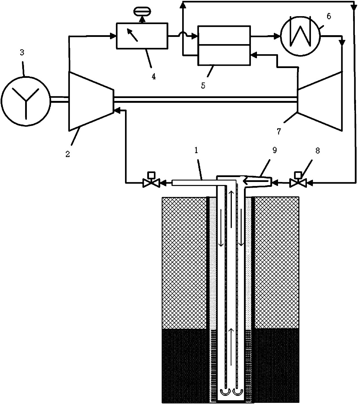
[0036] Such as figure 1 As shown, the S‐CO 2 Power generation system and method, the system consists of internal return pipe 1, S-CO 2 Gas turbine 2, generator 3, working fluid detection unit 4, regenerator 5, condenser 6, compressor 7, valve 8, outer layer descending pipe inlet 9, etc.; the system composition form is as follows: the compressor 7 will CO 2 compressed to a supercritical state and powers the CO 2 After being preheated by the regenerator 5, it enters the inlet 9 of the outer descending pipe section, and the valve 8 can cooperate to adjust the flow rate and pressure of the circulating working medium; the circulating working medium flows downward in the outer tube of the fin casing and absorbs rocks and hot dry rocks The heat in the heat is gathered to the inner return pipe 1 at the bottom of the heat extraction well; the heated circu...


PUM


Abstract

The invention discloses an S-CO2 power generation system and method for developing geothermal energy of hot dry rock based on a finned casing pipe. The finned casing pipe is a coaxial casing pipe, andthe system is composed of an outer-layer descending pipe segment, an outer-layer enhanced heat exchanging pipe segment, an inner backflow pipe, an S-CO2 gas turbine, a power generator, a compressor and the like. According to the innovation point of the S-CO2 power generation system and method for developing the geothermal energy of the hot dry rock based on the finned casing pipe, by means of closed-loop circulation of S-CO2 in the finned casing pipe, the geothermal energy is transmitted to the gas turbine from a hot dry rock layer; the finned casing pipe and the gas turbine both adopt the S-CO2 as circulating work media, and the heat exchanger end difference is eliminated; and fins are added outside a hot dry rock segment, the heat transfer area is increased, and the single well output is improved. The S-CO2 flows to the bottom of a heat taking well from the outer layer of a heat taking casing pipe to be collected to the inner layer, the geothermal energy in the hot dry rock is absorbed in the descending process, temperature ceaselessly rises, the S-CO2 then flows back to the ground from the inner layer, and the geothermal energy is converted into high-grade electric energy through the S-CO2 gas turbine and the power generator. After being detected by a work medium detecting unit and pressurized by the compressor, the S-CO2 starts new circulating, and sustainable exploitationof the geothermal energy of the hot dry rock is achieved.

Description

technical field [0001] The invention relates to the field of hot dry rock geothermal exploitation, in particular to S-CO2 based on finned casings for developing hot dry rock geothermal energy 2 (supercritical CO 2 ) power generation system and method. Background technique [0002] Geothermal energy is a green, low-carbon, recyclable and renewable energy. It has the characteristics of large reserves, wide distribution, cleanness, environmental protection, stability and reliability. It is a feasible and competitive clean energy. Geothermal energy is divided into shallow geothermal resources, hydrothermal geothermal resources and thermal dry rock resources. At present, both shallow and hydrothermal geothermal resources have been widely used, and thermal dry rock resources account for more than 95% of geothermal energy storage in my country. Not yet exploited. Hydrothermal geothermal resources have the problem of water level drop or resource depletion. The total amount of shal...

Claims


Application Information

Patent Timeline
IPC IPC(8): F03G4/00F24T10/17
CPCF03G7/04Y02E10/10
Inventor 邓世丰梁志远赵钦新王云刚
Owner XI AN JIAOTONG UNIV
Why Eureka
Try Eureka