

Heat-storage combustion device with double-valve-plate rotary valve
A regenerative combustion and rotary valve technology, applied in the field of regenerative combustion devices and regenerative combustion devices, can solve the problems of difficult sealing of rotary valves and large impact of exhaust gas leakage, so as to reduce the gap of gas leakage and improve the treatment of exhaust gas Efficiency, leakage prevention effect
- Summary
- Abstract
- Description
- Claims
- Application Information
AI Technical Summary
Problems solved by technology
Method used
Image

Examples
no. 1 example
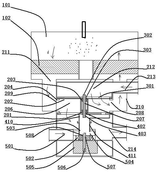
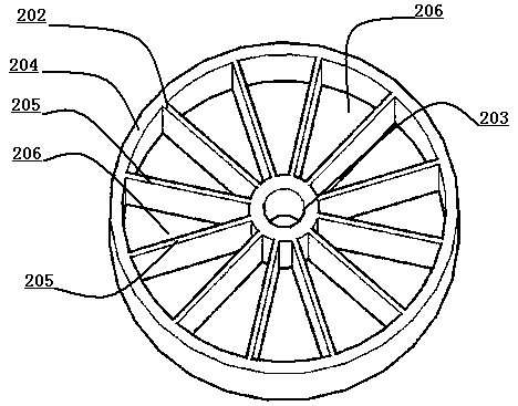
[0025] Such as figure 1 As shown, the regenerative combustion device with a double valve plate rotary valve includes: a combustion chamber 101 , a heat storage tank 102 and a double valve plate rotary valve 201 . The double valve plate rotary valve 201 includes: an annular gas distribution plate 202 , an air intake box 201 , an exhaust box 214 , a purge box 501 , an upper valve plate 301 and a lower valve plate 401 . Such as figure 2 As shown, several partition plates 205 are installed between the central bearing seat 203 and the outer ring body 204 of the annular gas distribution plate 202 , and a gas distribution chamber 206 is opened between the two partition plates 205 . Such as figure 1 As shown, the bearing support in the central bearing seat 203 is equipped with a synchronous rotating shaft 207, and the vent 208 of the air distribution chamber 206 is opened on the outer wall surface 209 of the outer ring body 204; The other end is connected with the vent 211 at the ...
no. 2 example
[0028] Such as Figure 5 As shown, an upper spring 601 is installed on the outside of the upper shaft body 303 of the synchronous rotating shaft 207 , and the upper spring 601 is movably fixed on the outside of the upper shaft body 303 by bolts 602 . A lower spring 603 is installed on the outside of the lower shaft body 403 of the synchronous rotating shaft 207 , and the lower spring 603 is movably fixed on the outside of the lower shaft body 403 by bolts 604 . The upper valve plate 301 is in close contact with the annular gas distribution plate 202 through the elastic force of the upper spring 601 ; the lower valve plate 401 is in close contact with the annular gas distribution plate 202 through the elastic force of the lower spring 603 . Such as Figure 6 As shown, an upper sealing groove 606 is formed on the upper wall surface 605 of the outer ring body 204 of the annular gas distributor 202 , and an upper sealing member 607 is installed in the upper sealing groove 606 . ...
PUM
 Abstract
Description
Claims
Application Information