
Spotting tooling for thermal vacuum test

A thermal vacuum test and tooling technology, which is used in thermometers and measuring devices that use electrical devices, electrical/magnetic components that are directly sensitive to heat, etc. Simple structure, easy to use and reliable, easy to make effect

Pending Publication Date: 2018-04-20
XI'AN INST OF OPTICS & FINE MECHANICS - CHINESE ACAD OF SCI
View PDF12 Cites 0 Cited by
  • Summary
  • Abstract
  • Description
  • Claims
  • Application Information

AI Technical Summary

Problems solved by technology

[0005] The purpose of the present invention is to provide a point layout tool for thermal vacuum test, which can conveniently collect and organize the drawn thermocouple wires, in order to solve the problems in the prior art that the outgoing lines at the test site are messy and the plug production process is time-consuming and laborious.

Method used


Image

  • Spotting tooling for thermal vacuum test
  • Spotting tooling for thermal vacuum test
  • Spotting tooling for thermal vacuum test

Examples


Embodiment Construction

[0032] The present invention will be further described in detail below in conjunction with the accompanying drawings and embodiments.

[0033] For the sake of convenience only, in the following description, specific directional terms, such as "up", "down", etc., are used with reference to the corresponding drawings, and should not be regarded as limiting the present invention. Where the defined orientation of the drawing is changed, the orientation indicated by these words shall be interpreted as a corresponding different orientation.

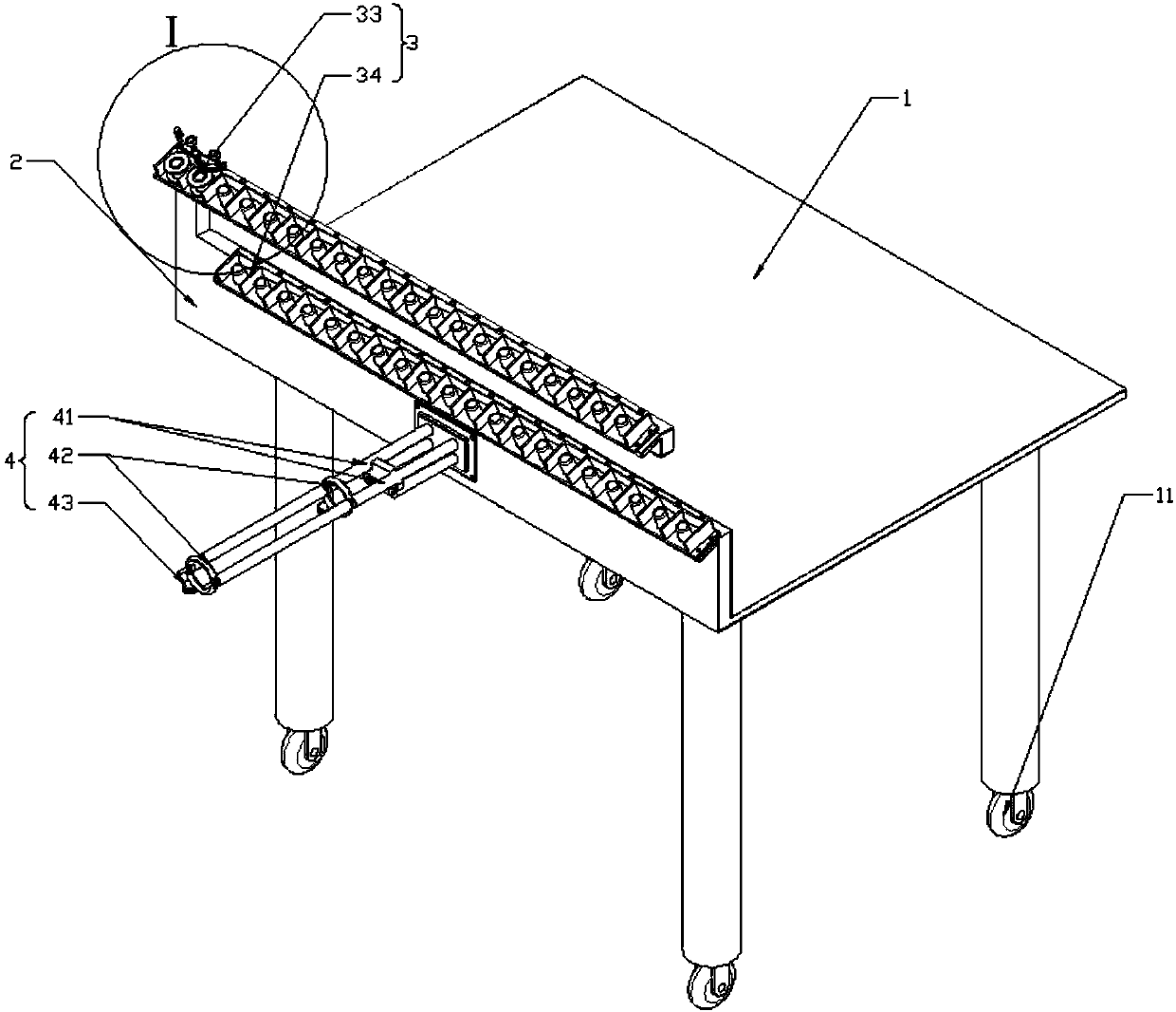
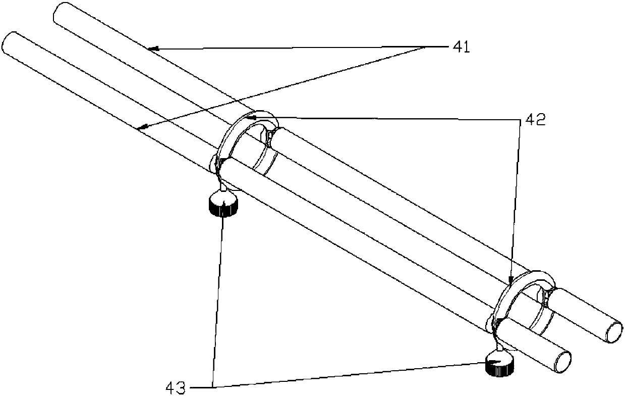
[0034] Such as figure 1 The shown a point layout tool for thermal vacuum test, including a workbench 1 with walking wheels 11, a bracket 2 installed on the workbench 1, and a bobbin frame 3 fixedly arranged on the bracket 2 from top to bottom and wire support assembly4.

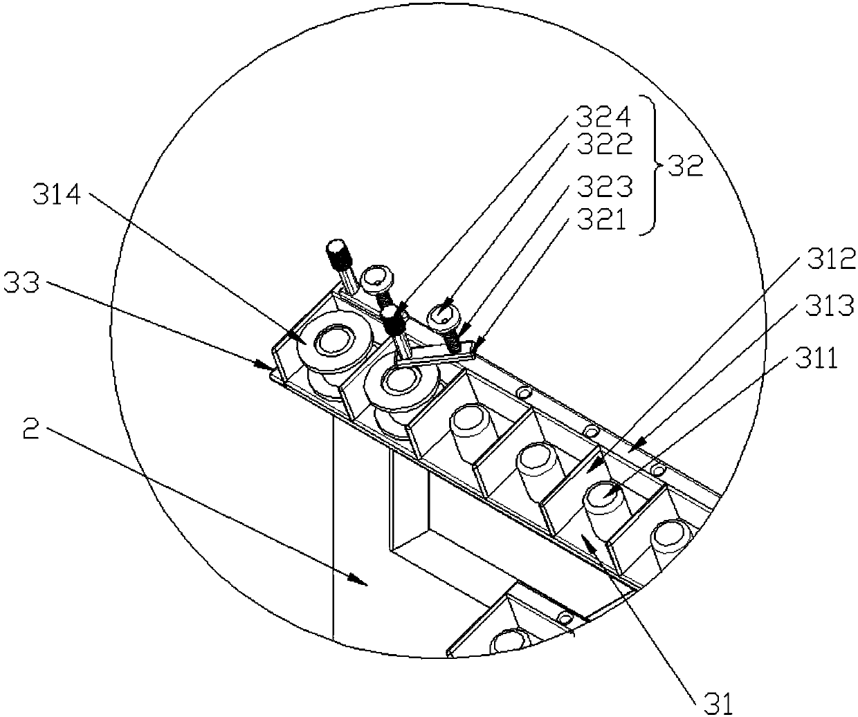
[0035] The creel 3 includes a first creel 33 and a second creel 34 in the form of horizontal strips, which are arranged in upper and lower layers. Such as figure 2 As sho...


PUM


Abstract

The invention relates to the field of aerospace thermal vacuum test technology, and aims to provide a spotting tooling for thermal vacuum test aiming at the problems of disorder on the test site and long time and great effort needed for the plug manufacturing process. The spotting tooling comprises a workbench, a bracket installed on the workbench, as well as a bobbin rack and a wire support assembly fixedly arranged on the bracket from the top to the bottom; the bobbin rack is in the form of a horizontal strip and comprises a plurality of bobbin holders, a heart through column for placing a bobbin is arranged on each bobbin holder, and the wire support assembly comprises two support rods and two wire guide rings; the wire guide rings are sleeved on the support rods, the wire guide ring comprises a first half ring and a second half ring, and the two ends of the first half ring are fixedly connected with the two support rods respectively; one end of the second half ring is hinged on onesupport rod, and the other end is a free end; when the second half ring is snapped on the first half ring, a gap through which a thermocouple wire passes is reserved between the end of the free end of the second half ring and the end of the first half ring.

Description

technical field [0001] The invention relates to the technical field of spaceflight thermal vacuum tests, in particular to a point layout tool for thermal vacuum tests. Background technique [0002] An important link in the environmental test of aerospace products is the thermal vacuum test. During the thermal vacuum test, the product needs to be put into a vacuum tank to make it undergo the rigorous test of cold and heat cycles in a vacuum environment. [0003] During testing, temperature monitoring is required at multiple points on the product. The temperature signal of each temperature monitoring point is transmitted outward through the thermocouple wire pasted on the thermocouple at this point. Due to the needs of the product and the test, often a test needs to paste dozens of sets of thermocouples on the product. Each group of thermocouples is derived from positive and negative two wires. According to past experience, each set of thermocouple wires will be coiled on ...

Claims


Application Information

Patent Timeline
Patent Type & Authority Applications(China)
IPC IPC(8): G01K7/02G01K1/14
CPCG01K1/14G01K7/02
Inventor 赵燕赛建刚王亚军高斌高博段炯张海民韩磊赵越贾琦孟宁飞
Owner XI'AN INST OF OPTICS & FINE MECHANICS - CHINESE ACAD OF SCI
Learn More