
A dual-mode dielectric filter

A technology of dielectric filter and dielectric resonator, which is applied in the direction of waveguide devices, circuits, electrical components, etc., can solve the problems that the accuracy of through holes and diameters cannot be guaranteed, affect the consistency of mass production, and have no ductility, etc., and achieve reduction Effects of commissioning time, size reduction, and assembly time reduction

Active Publication Date: 2019-11-29
WUHAN FINGU ELECTRONICS TECH
View PDF10 Cites 0 Cited by
  • Summary
  • Abstract
  • Description
  • Claims
  • Application Information

AI Technical Summary

Problems solved by technology

The disadvantage of this solution is that holes need to be drilled on the dielectric material. As we all know, ceramic materials have high hardness and no ductility. Therefore, it is impossible to precisely process through holes on the surface of ceramics by cutting like metal. At present, it is necessary to realize through holes. Holes can only be drilled on the green body before the ceramic is sintered, and then wound. However, during the sintering process, due to the shrinkage of the ceramic, the position accuracy and diameter accuracy of the final through hole cannot be guaranteed.
Thus affecting the consistency of mass production

Method used


Image

  • A dual-mode dielectric filter
  • A dual-mode dielectric filter
  • A dual-mode dielectric filter

Examples


Embodiment Construction

[0024] The present invention will be further described below in conjunction with the accompanying drawings and specific embodiments.

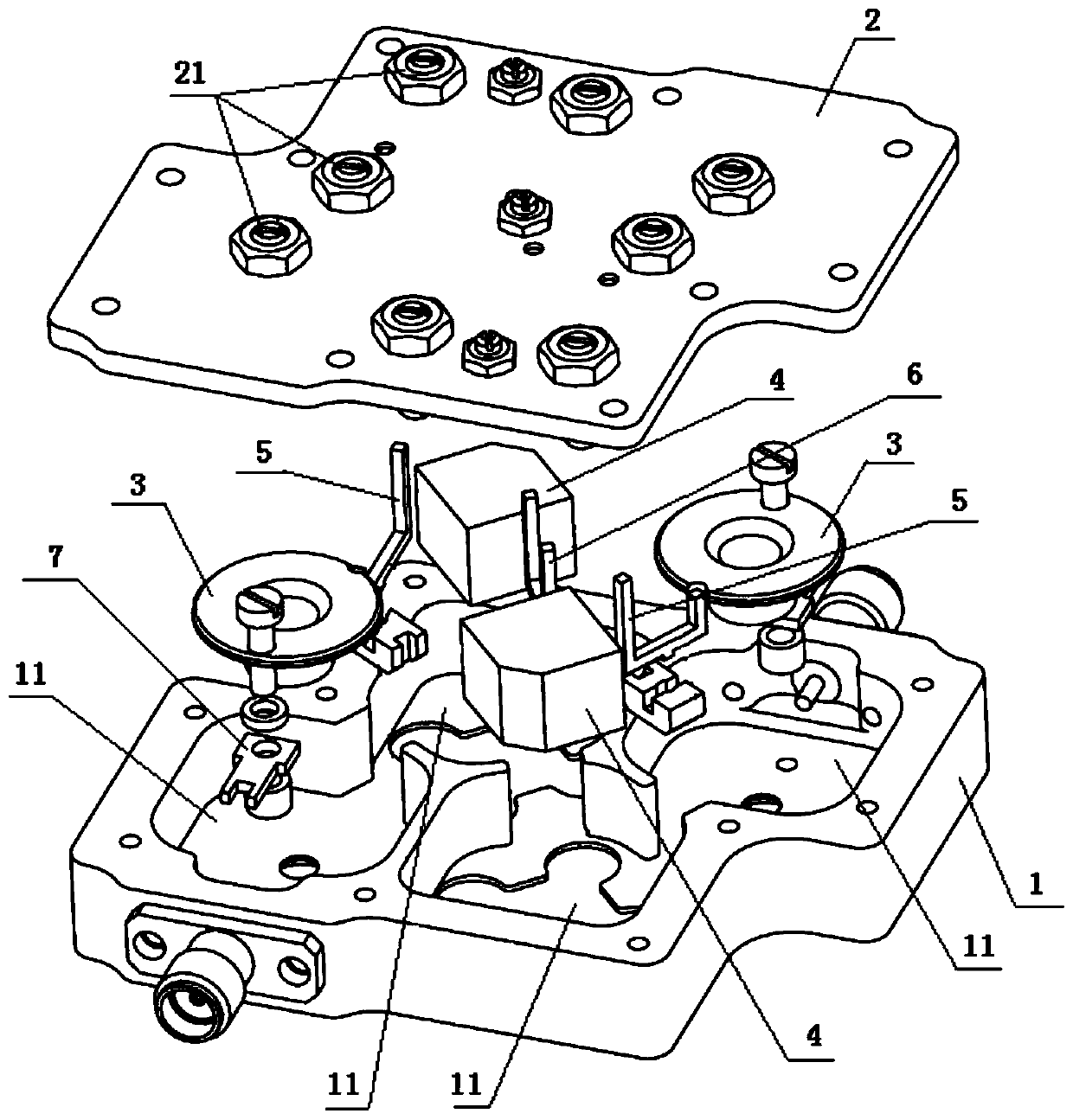
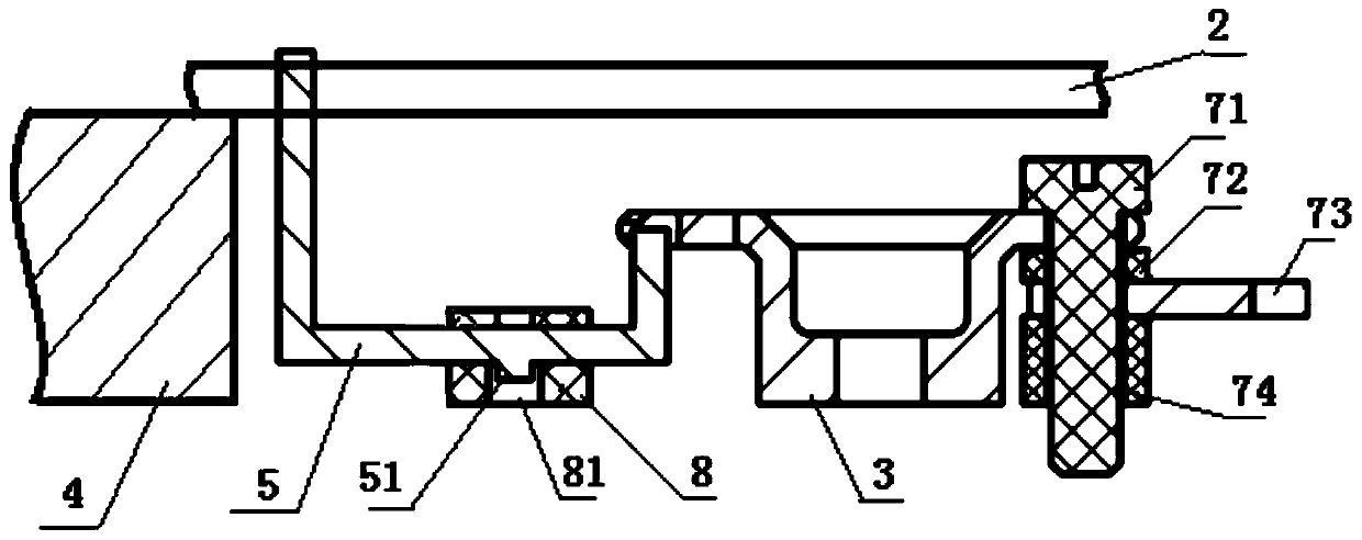
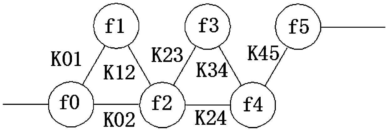
[0025] Such as figure 1 As shown, a dual-mode dielectric filter of the present invention includes a cavity body 1 and a cover plate 2, and the cover plate 2 is covered on the cavity body 1, and is fixedly connected by means of welding or crimping. Several inner cavities 11 are provided in the cavity 1, and in two adjacent inner cavities 11, a metal resonator 3 capable of generating a resonant frequency is provided in one of the inner cavities 11, and a metal resonator 3 that can generate a resonance frequency is provided in the other inner cavity 11. The dielectric resonator 4 capable of generating two resonant frequencies, the metal resonator 3 and the dielectric resonator 4 are not in contact with the corresponding inner cavity 11 wall, and the upper surface and the lower surface of the cover plate 2 are fixed by welding or crimping, etc. co...


PUM


Abstract

The invention relates to electronic parts and components in communication field, and particularly relates to a dual-mode dielectric filter. The filter comprises a cavity and a cover plate, wherein, inevery two adjacent inner cavities, one inner cavity is internally provided with a metal resonator capable of generating a resonant frequency, and the other inner cavity is internally provided with adielectric resonator capable of generating two resonant frequencies; a first coupling line is arranged between the metal resonator and the dielectric resonator, and a second coupling line is arrangedbetween every two adjacent dielectric resonators. The two degenerate mode resonant frequencies are generated through the dielectric resonators, and the functions of the two cavities can be achieved inthe filter, so that the dimensions can be obviously reduced under same indexes; the two degenerate mode resonant frequencies are independently controlled by the lengths of every two adjacent sides ofa dielectric block, the coupling quantity between two degenerate modes is controlled by the chamfer length of the dielectric block, and the electric parameters of the filter can be accurately controlled by controlling the boundary dimensions of the dielectric block, so that the batch uniformity is guaranteed, and the debugging time is reduced.

Description

technical field [0001] The invention relates to electronic components in the communication field, in particular to a double-mode dielectric filter. Background technique [0002] In recent years, with the increasing demand for high performance and miniaturization of communication equipment, dual-mode dielectric filters have received more and more attention. However, the previous dual-mode dielectric filters mostly used cylindrical resonators, and drilled through holes on the resonators for debugging. The disadvantage of this solution is that holes need to be drilled on the dielectric material. As we all know, ceramic materials have high hardness and no ductility. Therefore, it is impossible to precisely process through holes on the surface of ceramics by cutting like metal. At present, it is necessary to realize through holes. Holes can only be drilled on the green body before the ceramic is sintered, and then wound. However, during the sintering process, the position accura...

Claims


Application Information

Patent Timeline
Patent Type & Authority Patents(China)
IPC IPC(8): H01P1/20H01P1/208
CPCH01P1/2002H01P1/2082
Inventor 王一凡
Owner WUHAN FINGU ELECTRONICS TECH
Learn More