A Field Programmable Leaky Wave Antenna and Its Design Method

A design method and technology of leaky wave antennas, applied to antennas, antenna arrays, antenna grounding devices, etc., can solve problems such as time-consuming, and achieve the effects of short running time, reduced complexity and cost, and wide applicability

Active Publication Date: 2020-06-02
SOUTHEAST UNIV
View PDF8 Cites 0 Cited by
  • Summary
  • Abstract
  • Description
  • Claims
  • Application Information

AI Technical Summary

Problems solved by technology

Since the combination of codes is a huge number, each code takes a lot of time in commercial simulation software, so it is impossible to obtain the target code through exhaustive enumeration

Method used


Image

  • A Field Programmable Leaky Wave Antenna and Its Design Method
  • A Field Programmable Leaky Wave Antenna and Its Design Method
  • A Field Programmable Leaky Wave Antenna and Its Design Method

Examples


Embodiment Construction

[0033] In order to describe the technical solution disclosed in the present invention in detail, further elaboration will be made below in conjunction with the accompanying drawings and specific embodiments.

[0034] The present invention provides a low-profile field programmable leaky-wave antenna. The antenna first uses discrete code distribution to control the radiation field of the antenna. The code switching of the antenna can be directly driven by the digital voltage signal output by the FPGA, realizing the antenna and The direct integration of digital circuits greatly reduces the complexity and cost of the system.

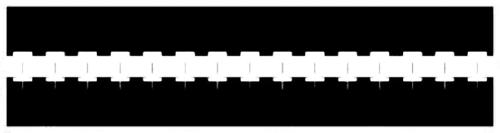
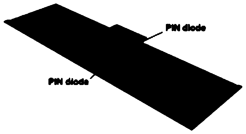
[0035] Such as figure 1 Shown is the overall structure of the antenna. The whole antenna is composed of multiple radiating units connected. The radio frequency signal is fed from both ends of the antenna to excite the quasi-TEM guided wave mode on the antenna. The interaction produces external radiation, and the radiation superposition of all units constitu...


PUM


Abstract

The invention discloses a site programmable leaky-wave antenna and a design method thereof. The antenna is formed by connecting a plurality of radiation units, radio frequency signals are fed from twoends of the antenna, a quasi TEM waveguide mode on the antenna is simulated, each radiation unit acts to generate external radiation during the waveguide travelling process, radiation of all units are superposed to form a total radiation field of the antenna, two parallel switch diodes are integrated on each radiation unit, and two radiation states can be generated by the unit by conduction and cutoff of the diodes. By independently controlling conduction and cutoff states of all units, control on the total field of the antenna can be achieved. The radiation field of the antenna is controlledby discrete code distribution, code switching of the antenna is driven by a digital voltage signal output from a field programmable gate array (FPGA), direct integration of the antenna and the digital circuit is achieved, and the complexity and the cost of the system are greatly reduced.

Description

technical field [0001] The invention relates to a field-programmable leaky-wave antenna with a low profile, in particular to a field-programmable leaky-wave antenna and a design method thereof. Background technique [0002] Reconfigurable antennas can be used in a variety of beamforming applications, such as 5G mobile communications, unmanned cars, unmanned aircraft, and smart logistics. However, the excitation source of most reconfigurable antennas currently adopts the illumination source, that is, the excitation source such as a horn is used to illuminate the aperture of the active antenna to form a reconfigurable reflected or transmitted beam. This will result in a large volume and weight of the whole antenna device, which is not convenient for practical application. [0003] In terms of the design of the leaky wave antenna, first of all, the leaky wave is the radiated electromagnetic wave generated by the traveling wave supported by the guiding wave structure during the...

Claims


Application Information

Patent Timeline
Patent Type & Authority Patents(China)
IPC IPC(8): H01Q1/38H01Q1/48H01Q1/50H01Q21/00
CPCH01Q1/38H01Q1/48H01Q1/50H01Q21/0087
Inventor 万向崔铁军
Owner SOUTHEAST UNIV
Why Eureka
Try Eureka