
A circularly polarized planar substrate integrated magnetoelectric dipole antenna and its array

A dipole antenna, planar-based technology, applied in the direction of separately energized antenna array, antenna array, electrical short antenna, etc., can solve the problems of narrowing bandwidth, increasing complexity, and difficult integration of millimeter-wave front-end circuit chips

Active Publication Date: 2020-12-25
SOUTHEAST UNIV
View PDF5 Cites 0 Cited by
  • Summary
  • Abstract
  • Description
  • Claims
  • Application Information

AI Technical Summary

Problems solved by technology

First, when most millimeter-wave substrate-integrated magnetoelectric dipoles are expanded into array antennas, their bandwidth tends to be significantly narrowed; second, most co-feed millimeter-wave substrate-integrated magnetoelectric dipoles Array antennas need to use more than three layers of dielectric substrates (excluding pasted dielectric materials), which increases the complexity of processing; third, most of the millimeter wave substrates integrate the feed network of the magnetoelectric dipole antenna array antenna They are all designed on thicker dielectric plates, so it is difficult to achieve direct integration with millimeter wave front-end circuit chips;

Method used


Image

  • A circularly polarized planar substrate integrated magnetoelectric dipole antenna and its array
  • A circularly polarized planar substrate integrated magnetoelectric dipole antenna and its array
  • A circularly polarized planar substrate integrated magnetoelectric dipole antenna and its array

Examples


Embodiment Construction

[0023] In order to further illustrate the technical solution disclosed in the present invention, the technical solution of the present invention will be further elaborated below in conjunction with specific embodiments and accompanying drawings.

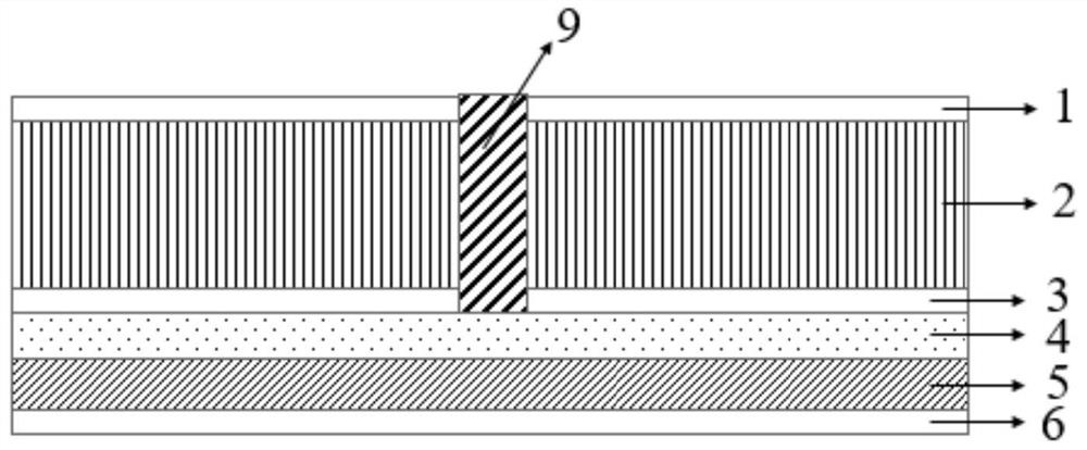
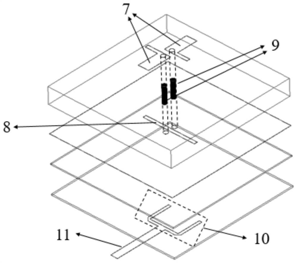
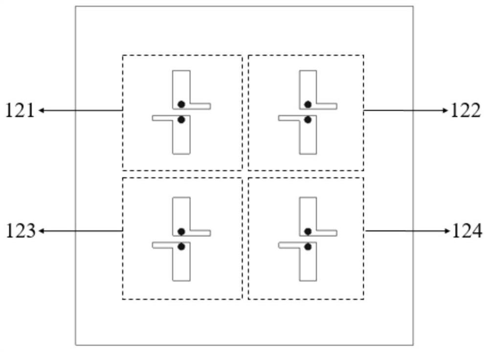
[0024] as attached figure 1 - attached figure 2 As shown, this specific embodiment discloses a circularly polarized planar substrate integrated magnetoelectric dipole antenna, including a top metal layer 1, a first dielectric layer 2, a middle metal layer 3, a second The second dielectric layer 4, the third dielectric layer 5, and the bottom metal layer 6; a pair of rotationally symmetrical L-shaped patches 7 are arranged at the center of the top metal layer 1, the middle metal layer 3 is a ground layer, and the middle metal layer A rectangular groove 8 is etched on the layer 3, and a pair of rotationally symmetrical L-shaped patches 7 and the middle metal layer 3 are electrically connected through a pair of metallized semi-blind h...


PUM


Abstract

The invention discloses a circularly polarized planar substrate integrated magnetoelectric dipole antenna and an array thereof. The antenna comprises a top metal layer, a first dielectric layer, a middle metal layer, a second dielectric layer, a third dielectric layer and a bottom metal layer which are sequentially arranged from top to bottom. A pair of L-shaped patches which are rotationally andsymmetrically arranged are arranged at the center of the top metal layer; the middle metal layer is a grounding layer, and a rectangular groove is etched in the middle metal layer; and the pair of L-shaped patches and the middle metal layer are electrically connected through a pair of metallized semi-blind holes penetrating through the first dielectric layer. The antenna carries out feeding through the low-profile microstrip feed structure, can be conveniently expanded into an array, and does not need to additionally arrange a dielectric layer to design a feed network. The ground antenna provided by the invention can obtain about 50% of impedance bandwidth, about 8% of 3dB axial ratio bandwidth and wider 3dB axial ratio beam width, and can realize direct integration with a millimeter waveradio frequency front-end circuit.

Description

technical field [0001] The invention belongs to microwave and millimeter wave communication, in particular to a circularly polarized planar substrate integrated magnetoelectric dipole antenna and an array thereof. Background technique [0002] mmWave technology has received tremendous attention in recent years, driven by various practical and potential applications, such as 5G mmWave communications, automotive radar, high-resolution imaging and detection, and some other applications. Compared with the microwave frequency band, the millimeter wave has greater loss in the process of propagating the same distance. Therefore, in terms of communication applications, the future millimeter wave communication is more for indoor short-distance access, high-speed point-to-point data transmission and other application scenarios. , at this time, a high-gain antenna will become indispensable. For radar applications, increasing the gain of the millimeter-wave radar antenna can effectivel...

Claims


Application Information

Patent Timeline
Patent Type & Authority Patents(China)
IPC IPC(8): H01Q9/28H01Q9/04H01Q1/38H01Q1/48H01Q1/50H01Q21/06H01Q21/00
CPCH01Q1/38H01Q1/48H01Q1/50H01Q9/0435H01Q9/0457H01Q9/285H01Q21/0075H01Q21/062H01Q21/065
Inventor 洪伟徐俊蒋之浩张慧
Owner SOUTHEAST UNIV
Learn More