
Smart home wireless power supply system and method

A technology of wireless power supply and wireless charging, applied in the direction of collectors, electric vehicles, electrical components, etc., can solve the problems of inconvenient movement, low charging efficiency, short charging distance, etc., to achieve convenient networking, wide coverage, improve The effect of efficiency

Pending Publication Date: 2018-04-20
青岛众海汇智能源科技有限责任公司
View PDF0 Cites 9 Cited by
  • Summary
  • Abstract
  • Description
  • Claims
  • Application Information

AI Technical Summary

Problems solved by technology

Although the wireless charging distance of the microwave energy transmission method is relatively long, due to the influence of microwave source power and cost, the transmission distance of wireless charging is generally about 5 meters, not more than 10 meters, which is not very far
Therefore, the common problems of wireless charging methods and technologies applied to smart homes in the market are: (1) the charging distance is very short and inconvenient to move; (2) the coverage of a single transmitter is small, and the charging efficiency is not high
[0004] Therefore, the existing smart home system still lacks a complete wireless power supply system to solve the problems existing in the existing wireless charging methods

Method used


Image

  • Smart home wireless power supply system and method
  • Smart home wireless power supply system and method
  • Smart home wireless power supply system and method

Examples


Embodiment Construction

[0031] Below, preferred embodiments of the present invention will be described in detail with reference to the accompanying drawings. Examples of these preferred embodiments are illustrated in the accompanying drawings. The embodiments of the present invention shown in the drawings and described based on the drawings are merely exemplary, and the technical spirit of the present invention and its main operations are not limited to these embodiments.

[0032] Here, it should also be noted that, in order to avoid obscuring the present invention due to unnecessary details, only the structures and / or processing steps closely related to the solution according to the present invention are shown in the drawings, and the related Other details are not relevant to the invention.

[0033] The wireless charging system and wireless charging method of the present invention will be described below by taking the application scenario of wireless charging in smart home as an example, but the pr...


PUM


Abstract

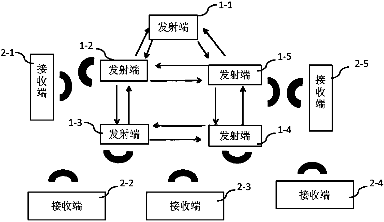
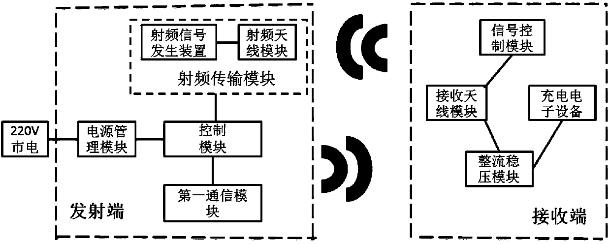
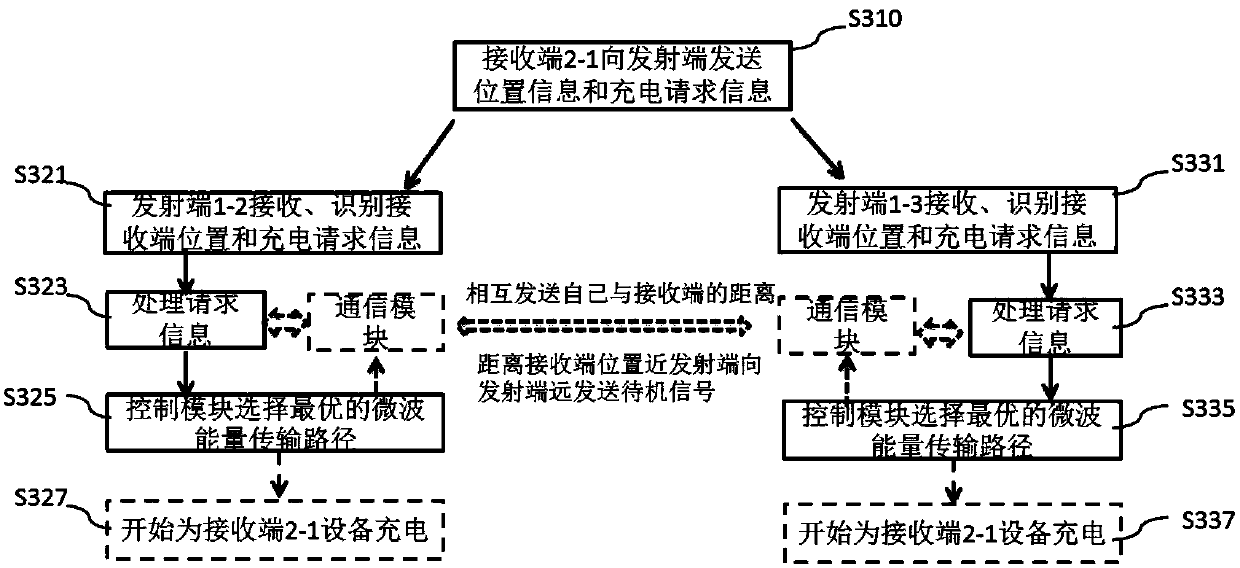
The present invention discloses a smart home wireless power supply system and method. The system comprises: a plurality of wireless power supply devices, each wireless power supply device is at leastconnected with adjacent wireless power supply devices overlapped with a power supply coverage range. Each wireless power supply device comprises: one radio-frequency transmission module configured togenerate and send microwave signals, wherein each radio-frequency transmission module comprises one radio-frequency signal generation device and one radio-frequency antenna module; one communication module configured to receive charging request signals from each wireless charging receiving terminal and position signals of each wireless charging receiving terminal; one control unit configured to determine whether the wireless charging receiving terminals are located in the power supply coverage range overlapped with the adjacent wireless power supply devices or not based on the position signalsand the distribution information of the wireless power supply devices in a wireless power supply node network and determine whether the wireless power supply devices charge the wireless charging receiving terminals or not when the wireless charging receiving terminals are located in the overlapped power supply coverage range. The smart home wireless power supply system and method are wide in coverage range, achieve intelligent charging and positioning track and improve the efficiency of wireless charging.

Description

technical field [0001] The invention belongs to the technical field of wireless power supply, and in particular relates to a smart home wireless power supply system and method. Background technique [0002] With the improvement of people's living standards and the accelerated pace of life, the concept of smart home has become more and more accepted by people, and intelligence has become more and more convenient for our lives. Wireless power supply technology is being favored by more and more smart home users because it converts wired power transmission into wireless power transmission, avoids complicated connection lines, effectively saves wires and cables, and is convenient for movement and operation. The wireless power supply system adopting the wireless power supply technology includes a wireless power supply transmitter and a wireless power supply receiver, and the wireless power supply transmitter wirelessly supplies power to the wireless power supply transmitter. [0...

Claims


Application Information

Patent Timeline
Patent Type & Authority Applications(China)
IPC IPC(8): H02J50/20H02J7/00
CPCH02J7/025H02J50/20
Inventor 刘超张定稳罗文宇孙会
Owner 青岛众海汇智能源科技有限责任公司
Learn More