Frequency drift compensation-based phase sensitive optical time domain reflectometer and measuring method thereof

A phase-sensitive optical and time-domain reflectometer technology, which is used in measuring devices, measuring ultrasonic/sonic/infrasonic waves, converting sensor outputs, etc., and can solve inaccurate information such as laser frequency drift, disturbance event location and frequency, and curve distortion. problem, to achieve the effect of accurate recovery and improved sensing performance

Active Publication Date: 2018-04-24
NANJING UNIV
View PDF8 Cites 31 Cited by
  • Summary
  • Abstract
  • Description
  • Claims
  • Application Information

AI Technical Summary

Problems solved by technology

In addition, due to the hysteresis of the temperature control system in the laser, the internal temperature of the laser will eventually fluctuate within a certain range, which will also cause the frequency drift of the laser
The frequency of the laser does not drift steadily to a single direction. The direction of the drift is random. Its drift trajectory is similar to random walk noise, and it can also produce a large drift in a short time, because the Φ-OTDR curve is for the frequency of the light source. Drift is relatively sensitive, so it will cause distortion of the Φ-OTDR curve, and the acquired information such as the position and frequency of the disturbance event will be inaccurate, thereby reducing the sensing performance of the Φ-OTDR system

Method used


Image

  • Frequency drift compensation-based phase sensitive optical time domain reflectometer and measuring method thereof
  • Frequency drift compensation-based phase sensitive optical time domain reflectometer and measuring method thereof
  • Frequency drift compensation-based phase sensitive optical time domain reflectometer and measuring method thereof

Examples


Embodiment Construction

[0034] The technical solutions of the present invention will be described in detail below in conjunction with the accompanying drawings.

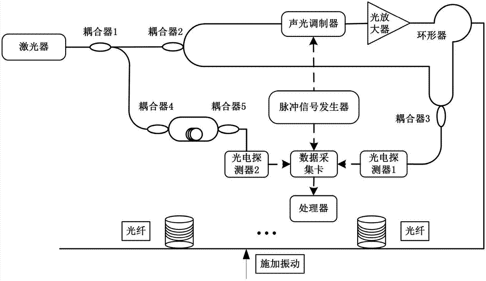
[0035] Such as figure 1 As shown, the phase-sensitive optical time domain reflectometer based on frequency drift compensation includes a narrow linewidth 1550nm laser, coupler 1, coupler 2, coupler 3, coupler 4, coupler 5, acousto-optic modulator, pulse signal A generator, an optical amplifier, a circulator, a sensing fiber, a connecting fiber, a delay fiber, a photodetector 1, a photodetector 2 and a data acquisition card. Coupler 2, acousto-optic modulator, pulse signal generator, optical amplifier, circulator, sensing fiber, coupler 3 and photodetector 1 form the Φ-OTDR sensing main module; coupler 4, connecting fiber, time delay The optical fiber, the coupler 5 and the photodetector 2 form a laser frequency drift detection module.

[0036]The output terminal of the narrow linewidth 1550nm laser is connected to the coupler 1 and is div...


PUM


Abstract

The invention discloses a frequency drift compensation-based phase sensitive optical time domain reflectometer and a measuring method thereof. According to the system, a Mach-Zehnder interferometer (MZI) with fixed arm length difference is formed and a laser frequency drift detection module is formed by introducing time delay optical fiber and connecting optical fiber with specific optical path difference on the basis of the traditional phi-OTDR. The frequency drift of the layer is obtained according to the signal intensity of the MZI in the system and the phase position of a phi-OTDR sensingsystem is compensated through a phase compensation algorithm, so that the influence on the sensing property of the phi-OTDR by the frequency drift of the laser is eliminated. The influence on the sensing property by the frequency drift of the laser is eliminated by constructing a novel phi-OTDR system, the influence of noise can be reduced by processing methods such as phase compensation, and theaccuracy of quantitatively measuring a vibration event by the system is improved.

Description

technical field [0001] The invention belongs to the technical field of optical fiber sensing, and in particular relates to a phase sensitive optical time domain reflectometer based on frequency drift compensation and a measuring method thereof. Background technique [0002] Phase Sensitive Optical Time Domain Reflectometry (Phase Sensitive Optical Time Domain Reflectometry, Φ-OTDR) has a fast response speed. It is a distributed optical fiber sensing technology that uses Rayleigh scattered light in the optical fiber. When the optical fiber is not disturbed by external events, the returned Rayleigh scattering signal in the optical fiber will present a stable coherent waveform, that is, the fluctuations on each optical power curve have the same shape and will not change with time. Conversely, if a certain place on the optical fiber is disturbed by an external event, the coherent waveform of the returned Rayleigh scattering signal will change, that is to say, the fluctuation sha...

Claims


Application Information

Patent Timeline
Patent Type & Authority Applications(China)
IPC IPC(8): G01D5/353G01H9/00
CPCG01D5/35329G01H9/004
Inventor 王峰袁泉张旭苹刘宇
Owner NANJING UNIV
Why Eureka
Try Eureka