Method for controlling quasi-Z resource inverter DC bus voltage based on straight-through duty ratio prediction

A DC bus voltage, source inverter technology, applied in the direction of converting AC power input to DC power output, electrical components, output power conversion devices, etc., can solve the problem of unfixed switching frequency, high switching frequency, large amount of calculation, etc. question

Active Publication Date: 2018-04-24
BEIHANG UNIV
View PDF6 Cites 15 Cited by
  • Summary
  • Abstract
  • Description
  • Claims
  • Application Information

AI Technical Summary

Problems solved by technology

[0008] The purpose of the present invention is to provide a method for controlling the direct-current bus voltage of a quasi-Z source inverter based on the straight-through duty ratio prediction, in order to solve the current control of the

Method used


Image

  • Method for controlling quasi-Z resource inverter DC bus voltage based on straight-through duty ratio prediction
  • Method for controlling quasi-Z resource inverter DC bus voltage based on straight-through duty ratio prediction
  • Method for controlling quasi-Z resource inverter DC bus voltage based on straight-through duty ratio prediction

Examples


Embodiment 1

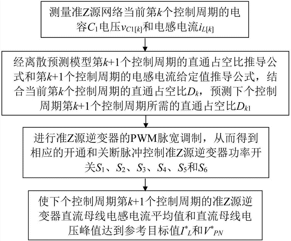
[0063] Such as figure 1 As shown, the control method for predicting the DC bus voltage of the quasi-Z source inverter based on the straight-through duty ratio disclosed in this embodiment includes: measuring the capacitance C of the current k-th control cycle of the quasi-Z source network 1 voltage v C1[k] and inductor current i L[k] ; The derivation formula of the direct duty ratio of the k+1th control cycle of the discrete prediction model and the derivation formula of the given value of the inductor current of the k+1th control cycle are combined with the direct duty cycle D of the current kth control cycle k , to predict the direct duty cycle D required for the k+1th control cycle of the next control cycle k1 ; Perform PWM pulse width modulation of the quasi-Z source inverter, so as to obtain the corresponding turn-on and turn-off pulses to control the power switch S of the quasi-Z source inverter 1 , S 2 , S 3 , S 4 , S 5 and S 6 ; Make the average value of the DC...

Embodiment 2

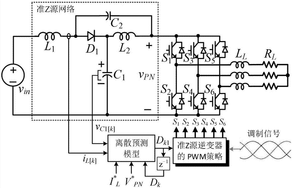
[0114] The method proposed in this embodiment based on the straight-through duty ratio to predict the DC bus voltage control method of the quasi-Z source inverter is based on figure 2 The quasi-Z source inverter shown and the proposed predictive control structure are simulated in MATLAB / Simulink. Among them, the inductance and capacitance of the quasi-Z source network are 500μH and 470μF respectively, and the reference target value of the inverter DC bus voltage required to maintain a constant value is V * PN =150V. In order to study the control of the DC bus voltage by the method proposed in this embodiment, during the simulation process, at 0.3s, the output DC voltage suddenly drops from 110V to 90V, Figure 5 is the DC supply voltage v in , predicting the resulting shoot-through duty cycle D, capacitance C 1 voltage v C1 , and the DC bus voltage v PN Simulation results under the predictive control proposed in this embodiment; Figure 6 and 7 They are the simulation...


PUM


Abstract

The invention discloses a method for controlling quasi-Z resource inverter DC bus voltage based on straight-through duty ratio prediction. Through measuring values of inductor current and capacitor voltage of a current control cycle, combined with an expected DC bus voltage value, based on an established prediction model, a straight-through duty ratio needed by a next control cycle is directly predicted for a modulator, a corresponding switching function is outputted to an inverter bridge under the modulation strategy of a quasi-Z source inverter, and a fixed switching frequency is obtained. Since the evaluation of an evaluation function for each switching state is not needed, the computational load is greatly reduced, and the corresponding control can be completed without a high switchingfrequency. Since the switching function is obtained through the modulator, the switching frequency is fixed, and the switching function and a PI adjustor can use the same modulator. The control strategy instantly responds to the state of the next control cycle based on the voltage and current at the moment, and the dynamic response for a system is quick.

Description

technical field [0001] The invention relates to the technical field of power electronic conversion, in particular to a method for controlling the direct current bus voltage of a quasi-Z source inverter based on a straight-through duty ratio. Background technique [0002] The quasi-Z source inverter overcomes the limitation of the step-up ratio of the traditional inverter due to the single-stage conversion, and its direct state does not require dead-zone control, which greatly simplifies debugging, reduces output-side interference, and improves the stability of the inverter system . The quasi-Z source inverter boosts the output voltage of the DC power supply by inserting a straight-through state in the inverter bridge of the traditional inverter, that is, the upper and lower switching tubes of the same bridge arm are turned on at the same time. In order to obtain a stable output voltage on the AC side, the control of the DC bus voltage of the quasi-Z source inverter is parti...

Claims


Application Information

Patent Timeline
IPC IPC(8): H02M7/5387H02M1/088
Inventor 刘钰山
Owner BEIHANG UNIV
Why Eureka
Try Eureka