Bar milling cutter

A technology of milling cutters and sipes, which is applied in the field of rod milling cutters, can solve the problems of affecting machining, low machining accuracy, and easy shaking of the blade, and achieve the effects of saving maintenance and replacement, high flatness, and overcoming low machining accuracy

Active Publication Date: 2018-04-27
常州丹姆德工具制造有限公司
View PDF6 Cites 3 Cited by
  • Summary
  • Abstract
  • Description
  • Claims
  • Application Information

AI Technical Summary

Problems solved by technology

[0002] Rod milling cutter is a rotating tool with one or more teeth for milling. When working, each tooth cuts off the allowance of the workpiece intermittently. The milling cutter is mainly used for machining planes, steps, Grooves, forming surfaces and cutting off workpieces, etc., according to work needs, milling cutters can be divided into cylindrical milling cutters, face milling cutters, end mills, etc. Existing plane milling cutters generally have a milling cutter body and multiple corresponding settings The cutter body on the cutter head is usually provided with holes on the front or side of the cutter body for bolts to pass through, so that each cutter body can be detachably installed in the accommodation groove of the milling cutter body, and the cutter body will be worn due to the milling process or when damaged, the blade can be directly replaced. In the prior art, for example, the invention patent of application number 201310465840.0 includes a blade, a cutter head, a knife neck, a knife handle, and a positioning thread. It is characterized in that the front end of the knife neck is set The cutter head, the front end of the cutter head is provided with a blade, the rear end of the cutter neck is provided with a handle, and the outside of the handle is provided with positioning threads. Although the invention has a simple structure, there are many shortcomings and defects. In the existing equipment, when the milling cutter works When the blade is subjected to a large impact force, the fastening screw is difficult to support for a long time, the blade is easy to shake, the machining accuracy is low, and there are defects in the design that affects the accuracy of machining. In view of these situations, in order to avoid the above technical problems, it is necessary A rod milling cutter is provided to overcome said drawbacks of the prior art

Method used


Image

  • Bar milling cutter
  • Bar milling cutter
  • Bar milling cutter

Examples


Embodiment Construction

[0015] The following will clearly and completely describe the technical solutions in the embodiments of the present invention with reference to the accompanying drawings in the embodiments of the present invention. Obviously, the described embodiments are only some, not all, embodiments of the present invention. Based on the embodiments of the present invention, all other embodiments obtained by persons of ordinary skill in the art without making creative efforts belong to the protection scope of the present invention.

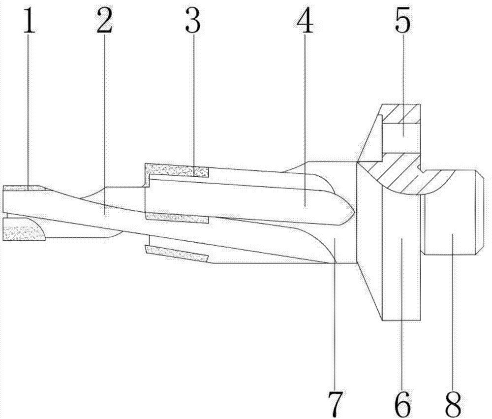
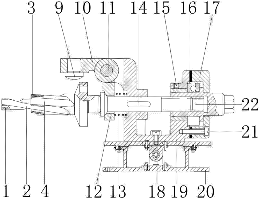
[0016] see Figure 1-3 , the present invention provides a technical solution: a rod milling cutter, including a convex cutter 1, the material of the convex cutter 1 is stainless steel, used for turning and milling channels or grooves, the inner wall of the convex cutter 1 is provided with a knife groove 2, used In order to export the cutting chips, the outer wall of the sipe 2 is connected with the inner wall of the convex knife 1. A flat knife 3 is arranged o...


PUM


Abstract

The invention discloses a bar milling cutter. A convex cutter is included; a cutter groove is formed in the inner wall of the convex cutter; the outer wall of the cutter groove is connected with the inner wall of the convex cutter; a flat cutter is arranged on the outer side of the cutter groove; a material guiding groove is formed in the outer wall of the flat cutter; the outer wall of the material guiding groove is connected with the inner wall of the flat cutter; and a cutter body is arranged on the inner wall of the material guiding groove. According to the bar milling cutter, due to cooperation among the convex cutter, the cutter groove, the flat cutter and the material guiding groove, under the effects of an impeller, a notch and a hole channel of a machined workpiece are machined bythe convex cutter, and cut down fragments can be brought out by the cutter groove during cutter retracting; in order to prevent tripping of a cutter handle in a high-speed rotating state, a clampingarm is pressed downwards to fix a sleeve, and therefore the defects that a tool bit of a traditional bar milling cutter cannot be fast replaced, and tool bit connection is not stable can be overcome,the machining steps are simplified, the overhauling and replacing time is saved for an operator, the work difficulty is reduced for the operator, the work fatigue of the operator is overcome, and thebar milling cutter is applicable to application and popularization.

Description

technical field [0001] The invention relates to the technical field of machining, in particular to a rod milling cutter. Background technique [0002] Rod milling cutter is a rotating tool with one or more teeth for milling. When working, each tooth cuts off the allowance of the workpiece intermittently. The milling cutter is mainly used for machining planes, steps, Grooves, forming surfaces and cutting workpieces, etc., according to work needs, milling cutters can be divided into cylindrical milling cutters, face milling cutters, end mills, etc. The existing flat milling cutters generally have a milling cutter body and multiple corresponding settings The cutter body on the cutter head is usually provided with holes on the front or side of the cutter body for bolts to pass through, so that each cutter body can be detachably installed in the accommodation groove of the milling cutter body, and the cutter body will be worn due to the milling process or when damaged, the blade...

Claims


Application Information

Patent Timeline
Patent Type & Authority Applications(China)
IPC IPC(8): B23C5/10
CPCB23C5/109
Inventor 梁荣强
Owner 常州丹姆德工具制造有限公司
Why Eureka
Try Eureka