
Method for treating printing and dyeing wastewater in textile factory

A printing and dyeing wastewater and textile factory technology, applied in the field of printing and dyeing wastewater treatment equipment, can solve the problem of inconvenient transportation of sludge and achieve the effect of convenient transportation

Inactive Publication Date: 2018-04-27
刘丽影
View PDF0 Cites 2 Cited by
  • Summary
  • Abstract
  • Description
  • Claims
  • Application Information

AI Technical Summary

Problems solved by technology

[0002] Printing and dyeing wastewater refers to the wastewater generated during pretreatment, dyeing, printing and finishing of textiles such as cotton, wool and chemical fibers. The main sources of printing and dyeing wastewater are desizing wastewater, scouring wastewater, bleaching wastewater and Mercerized wastewater, due to the deep color of printing and dyeing wastewater, it is necessary to treat printing and dyeing wastewater. The treatment method of printing and dyeing wastewater includes the following steps: degradation treatment of hydrolytic acidification tank, denitrification treatment of anoxic tank, denitrification of anaerobic tank Phosphorus treatment and degradation treatment in the aerobic tank, the printing and dyeing wastewater treatment method can effectively remove the toxic and refractory substances in the printing and dyeing wastewater, and the process operation is simple, but the sludge in the aerobic tank is directly discharged, and there is no Deep processing, and the sludge produced in the aerobic tank is not easy to transport

Method used


Image

  • Method for treating printing and dyeing wastewater in textile factory

Examples


Embodiment

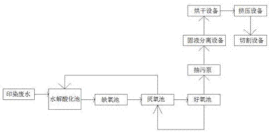
[0027] refer to figure 1 , a method for the treatment of printing and dyeing wastewater in textile mills is proposed in this embodiment, comprising the following steps:

[0028] S1: The printing and dyeing wastewater is first passed into the hydrolytic acidification tank, and the brevis and Alicyclobacillus inoculated in the hydrolytic acidification tank degrade the macromolecular organic matter in the printing and dyeing wastewater;

[0029] S2: The wastewater treated in the hydrolytic acidification tank described in S1 is passed into the anoxic tank, and the Bacillus cereus and Pseudomonas cerevisiae inoculated in the anoxic tank are used for denitrification treatment of the wastewater;

[0030] S3: The wastewater treated in the anoxic pool described in S2 is passed into the anaerobic pool, and the ethanol thermophilic anaerobic bacteria inoculated in the anaerobic pool are used to remove nitrogen and phosphorus from the wastewater. The denitrification acid solution is pass...


PUM


Abstract

The invention discloses a method for treating printing and dyeing wastewater in textile mills, which comprises the following steps: S1: the printing and dyeing wastewater is first passed into a hydrolytic acidification pool, and the brevis and Alicyclobacillus inoculated in the hydrolytic acidification pool are used to treat the printing and dyeing wastewater The macromolecular organic matter in the water is degraded, and the wastewater treated in the hydrolytic acidification tank described in S2:S1 is passed into the anoxic tank, and the Bacillus cereus and Pseudomonas cerevisiae inoculated in the anoxic tank detoxify the wastewater Nitrogen treatment, S3: The wastewater treated in the anoxic tank described in S2 is passed into the anaerobic tank, and the ethanol thermophilic anaerobic bacteria inoculated in the anaerobic tank perform nitrogen and phosphorus removal treatment on the wastewater. The invention is economical and practical, and the sludge produced in the aerobic tank is sequentially processed through solid-liquid separation equipment, drying equipment, extrusion equipment and cutting equipment, and the sludge produced in the aerobic tank finally becomes small solid sludge , making the sludge produced in the aerobic tank easy to transport.

Description

technical field [0001] The invention relates to the technical field of printing and dyeing wastewater treatment equipment, in particular to a method for treating printing and dyeing wastewater in textile mills. Background technique [0002] Printing and dyeing wastewater refers to the wastewater generated during pretreatment, dyeing, printing and finishing of textiles such as cotton, wool and chemical fibers. The main sources of printing and dyeing wastewater are desizing wastewater, scouring wastewater, bleaching wastewater and Mercerized wastewater, due to the deep color of printing and dyeing wastewater, it is necessary to treat printing and dyeing wastewater. The treatment method of printing and dyeing wastewater includes the following steps: degradation treatment of hydrolytic acidification tank, denitrification treatment of anoxic tank, denitrification of anaerobic tank Phosphorus treatment and degradation treatment in the aerobic tank, the printing and dyeing wastewat...

Claims


Application Information

Patent Timeline
IPC IPC(8): C02F3/34C02F3/30C02F11/12C02F101/10C02F101/16C02F101/30C02F103/30
CPCC02F3/34C02F3/30C02F11/121C02F2101/10C02F2101/16C02F2101/30C02F2103/30
Inventor 刘丽影
Owner 刘丽影
Learn More