Water vapor generating device for laboratory

A technology of water vapor generation and water vapor generator, applied in steam generation, steam generation methods, steam boilers, etc., can solve problems such as difficult to achieve continuous and stable supply of trace water vapor, achieve increased body specific surface area, stable evaporation rate, The effect of enhancing the evaporation effect

Active Publication Date: 2018-04-27
ANHUI UNIVERSITY OF TECHNOLOGY
View PDF6 Cites 0 Cited by
  • Summary
  • Abstract
  • Description
  • Claims
  • Application Information

AI Technical Summary

Problems solved by technology

[0006] The purpose of the present invention is to overcome the problem that the existing device is difficult to realize the stable supply of continuous trace water vapor, and to provide a laboratory water vapor generating device, through the speed regulation type The peristaltic pump can stably control the supply volume and supply rate of distilled water, the steam generator can stably evaporate, and can supply continuous trace water vapor stably, meeting the requirements of the experiment

Method used


Image

  • Water vapor generating device for laboratory
  • Water vapor generating device for laboratory
  • Water vapor generating device for laboratory

Examples


Embodiment 1

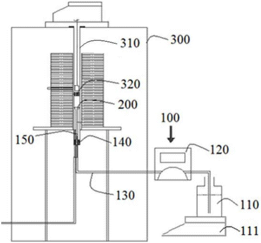
[0038] Refer to attached figure 1 , figure 2 with Figure 5As shown, a laboratory water vapor generating device of this embodiment includes an infusion unit 100, an evaporation unit 200 and a heating furnace 300, the infusion unit 100 and the evaporation unit 200 are connected through a liquid supply pipe 130, and the evaporation unit 200 is arranged in the heating furnace 300 inside the quartz tube 310 . The infusion unit 100 is used to deliver the distilled water required for the experiment, the evaporation unit 200 is used to evaporate the distilled water, and the heating furnace 300 is used to provide the temperature required for evaporation.

[0039] The infusion unit 100 in the present embodiment comprises a beaker 110 and a speed-regulating peristaltic pump 120, the beaker 110 and the speed-regulating peristaltic pump 120 are connected through a liquid supply pipe 130, the beaker 110 is used to store distilled water, and the lower end of the beaker 110 is provided wi...

Embodiment 2

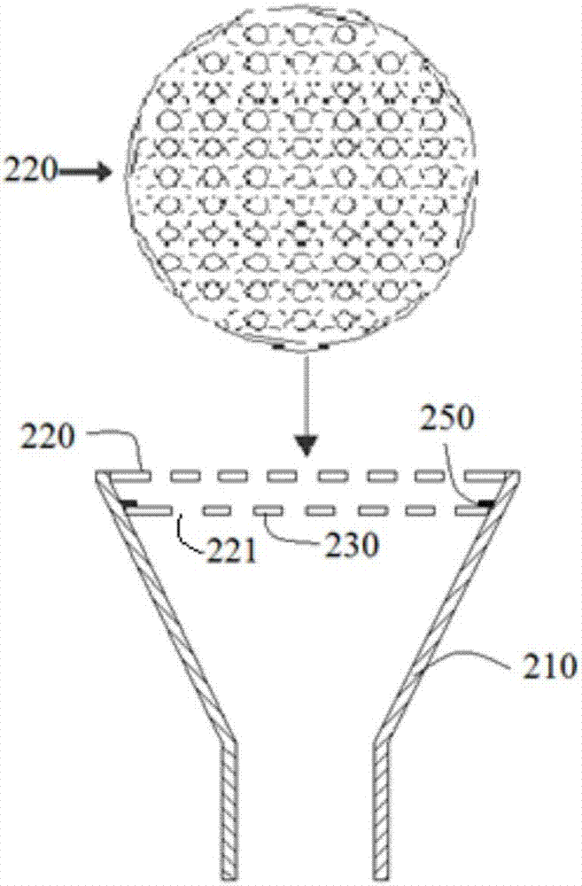
[0046] Refer to attached figure 1 , image 3 and Figure 5 As shown, a laboratory water vapor generating device of this embodiment is basically the same as that of Embodiment 1, except that the lower stabilizing plate 230 is arranged in the water vapor generator 210, and the lower The stabilizing plate 230 can float up and down in the steam generator 210 along with the height of the liquid level; The needle 250 and the contact probe 250 are set on the side wall of the water vapor generator 210. When the lower stabilizer plate 230 floats up with the rise of the liquid level, it will touch the contact probe 250. At this time, the speed-regulating type peristalsis will be reduced. The power of the pump 120 is reduced to prevent the liquid level from being too high.

[0047] Make the highest liquid level in the water vapor generator 210 still lower than the upper surface of the lower stabilizing plate 230; on the one hand, avoid water overflowing the evaporation unit 200; When...

Embodiment 3

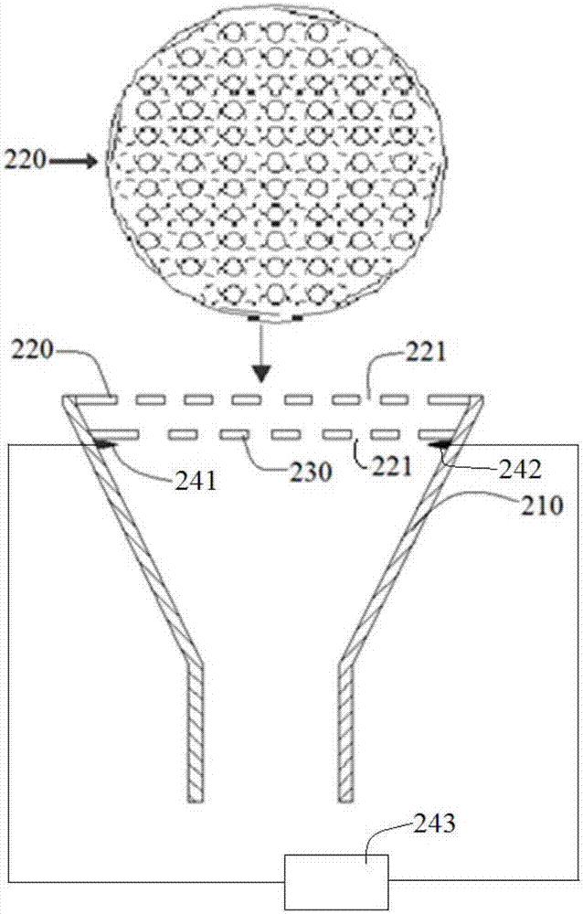
[0049] Refer to attached figure 1 , Figure 4 and Figure 5 As shown, a laboratory water vapor generating device of the present embodiment is basically the same as that of Embodiment 1, the difference is that: the inner side of the circular hole 221 is provided with a thorn 222, and the thorn 222 is formed by the circular hole 221. The inner wall extends toward the center, so that when the splashed liquid drops pass through the circular hole 221 , it still collides with the thorns 222 inside the circular hole 221 , preventing the splashed liquid from passing through the circular hole 221 smoothly.

[0050] In addition, it is worth noting that the spurs 222 are set as long spurs and short spurs with staggered lengths and short spurs. The staggered distribution of long spurs and short spurs can not only fully contact the droplets passing through the round hole 221, but also avoid the droplet passing through the round hole 221. round hole 221, and can ensure the permeability of...


PUM


Abstract

The invention discloses a water vapor generating device for a laboratory, and belongs to the technical field of vapor generation. The water vapor generating device comprises a liquid conveying unit, an evaporating unit and a heating furnace, wherein the liquid conveying unit comprises a beaker and a speed-regulating type peristaltic pump; the evaporating unit comprises a funnel-shaped water vaporgenerator; the upper end of the water vapor generator is equipped with an upper steady-flow sheet and a lower steady-flow sheet; circular holes are uniformly distributed in each of the upper steady-flow sheet and the lower steady-flow sheet; a vertical quartz tube is arranged in the heating furnace; and the water vapor generator is vertically arranged inside the quartz tube. According to the watervapor generating device disclosed by the invention, water supply amount and supply speed of distilled water can be stably controlled, and the upper steady-flow sheet and the lower steady-flow sheet with staggered circular holes in the water vapor generator can be used for stably evaporating distilled water and preventing the distilled water from being splashed, so that experimental requirements are met.

Description

technical field [0001] The invention belongs to the technical field of steam generation, in particular to a laboratory water steam generation device. Background technique [0002] Water vapor is a common gas during metallurgical reactions. Iron workers Lee S (Lee S, Jung J, Kim K. Improvement of reduction of iron ore using hydrogen-enriched synthetic gas [J]. CAMP ISIJ, 2009, 22 (1): 266-273.) and Guo Tonglai (Guo Tonglai .Mathematical simulation of the new low-carbon ironmaking process of blast furnace injection of coke oven gas[D].Northeastern University, 2015.) Through the calculation and experimental research of the material balance and heat balance in each area of ​​the blast furnace under different new ironmaking process conditions, it is found that with With the increase of the amount of coal injection or the proportion of natural gas injection, the CO, H in the blast furnace gas 2 content increased significantly, H 2 H produced by reducing ore 2 The O content als...

Claims


Application Information

Patent Timeline
Patent Type & Authority Applications(China)
IPC IPC(8): F22B1/00F22B37/00F22D5/32
CPCF22B1/00F22B37/00F22D5/32
Inventor 万勇赵晴晴吴义超李杰张立强吴朝阳王伟胜
Owner ANHUI UNIVERSITY OF TECHNOLOGY
Why Eureka
Try Eureka