Fuel gas type equipment

A gas-fired and equipment technology, applied in the field of metallurgy, can solve problems such as high labor intensity, and achieve the effects of reducing heat loss, low energy consumption, and cost reduction

Pending Publication Date: 2018-04-27
SHENWU TECH GRP CO LTD
View PDF0 Cites 0 Cited by
  • Summary
  • Abstract
  • Description
  • Claims
  • Application Information

AI Technical Summary

Problems solved by technology

The existing gas-fired vacuum equipment uses manual slag removal, tank cleaning, material loading, and magnesium extraction during production. Due to its structure, the labor intensity is relatively high

Method used


Image

  • Fuel gas type equipment
  • Fuel gas type equipment
  • Fuel gas type equipment

Examples


Embodiment Construction

[0027] In order to make the purpose, technical solution and advantages of the present invention clearer, the present invention will be further described in detail below in conjunction with specific embodiments and accompanying drawings. It should be understood that the specific embodiments described here are only used to explain the present invention, not to limit the present invention.

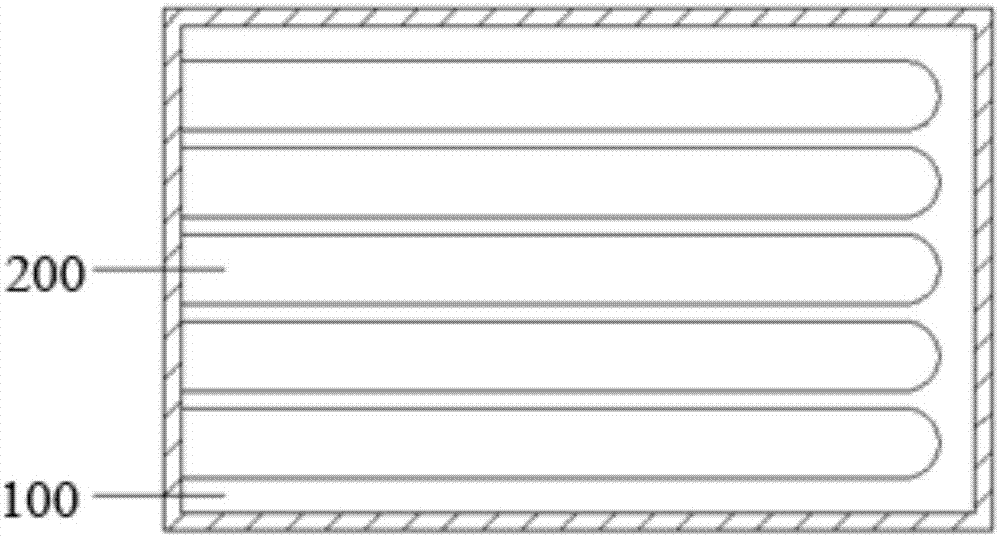
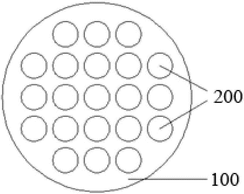
[0028] Metal oxides and metal minerals have high melting points, so they cannot be sucked into the vacuum reaction chamber after melting like alloys. The feeding and retrieving of metal oxides and metal minerals must open the vacuum reaction chamber. The invention adopts a detachable reaction chamber, which makes the structure of the equipment more flexible and convenient, and is especially suitable for the reduction of metal oxides and metal minerals.

[0029] refer to figure 1 and figure 2 , which schematically shows the combustion chamber 100 and its internal structure. The combustion...


PUM


Abstract

The invention discloses a gas type equipment, which comprises a combustion chamber and a reaction chamber, and the reaction chamber is detachably arranged in the combustion chamber. The equipment of the present invention can increase the number of reaction chambers and combustion chambers according to the amount of materials to be processed, and all reaction chambers can share one combustion chamber for heating, and only need to increase the number of burners and flue gas pipes to achieve uniform heating Purpose.

Description

technical field [0001] The invention relates to the field of metallurgy, in particular to a gas-fired device. Background technique [0002] The existing small and medium-sized vacuum furnaces are mainly electric heating. Electricity is a secondary energy source. Generally, the power generation efficiency of fuel is 30%-35%, and the thermal efficiency of electric energy is generally 80%-85%. Therefore, the thermal efficiency of fuel electric energy is 25%. % or so (<30%). For experimental vacuum furnaces, electric heating is convenient and clean, but for industrialized large-scale vacuum equipment, energy saving is a problem that must be considered. [0003] High temperature air combustion technology (HTACT) is an advanced combustion technology with high efficiency, energy saving and environmental protection that developed rapidly in the 1990s. The existing gas-fired vacuum equipment uses manual slag removal, tank cleaning, material loading, and magnesium extraction duri...

Claims


Application Information

Patent Timeline
Patent Type & Authority Applications(China)
IPC IPC(8): F23D14/12F23D14/46
CPCF23D14/12F23D14/46
Inventor 李康宋敏洁郭科宏王东方石为华吴道洪
Owner SHENWU TECH GRP CO LTD
Why Eureka
Try Eureka