
Reaction tank for wafer etching

A reaction tank and wafer technology, which is applied in electrical components, semiconductor/solid-state device manufacturing, circuits, etc., can solve the problems of high etching rate at the bottom of the wafer and low etching rate at the top of the wafer, and achieve the goal of improving the surface quality of the wafer Effect

Active Publication Date: 2018-04-27
YANGTZE MEMORY TECH CO LTD
View PDF14 Cites 5 Cited by
  • Summary
  • Abstract
  • Description
  • Claims
  • Application Information

AI Technical Summary

Problems solved by technology

When the wafer etching process is short, the etching unevenness of the wafer surface is not obvious, but when the wafer is soaked in the acid bath solution for a long time, the etching unevenness of the wafer surface will stand out as a high etch rate at the bottom of the wafer and a low etch rate at the top of the wafer

Method used


Image

  • Reaction tank for wafer etching
  • Reaction tank for wafer etching
  • Reaction tank for wafer etching

Examples


Embodiment Construction

[0026] Exemplary embodiments of the present disclosure will be described in more detail below with reference to the accompanying drawings. Although exemplary embodiments of the present disclosure are shown in the drawings, it should be understood that the present disclosure may be embodied in various forms and should not be limited by the embodiments set forth herein. Rather, these embodiments are provided for more thorough understanding of the present disclosure and to fully convey the scope of the present disclosure to those skilled in the art.

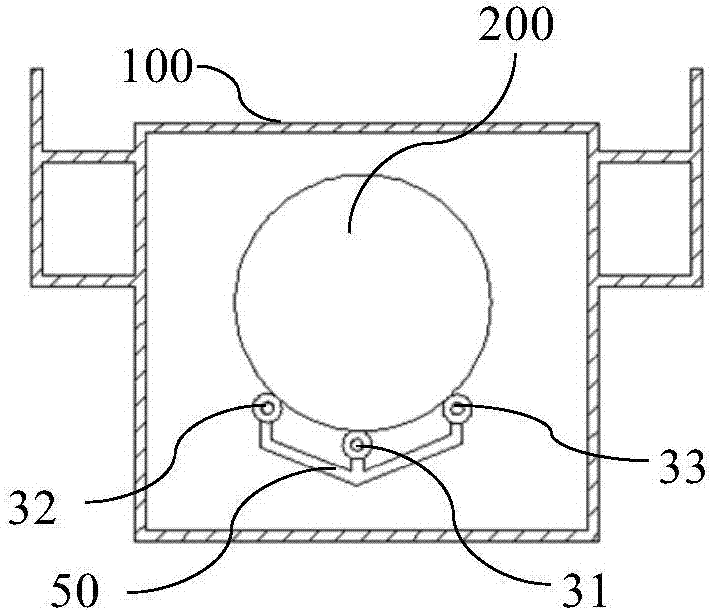
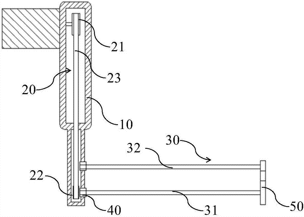
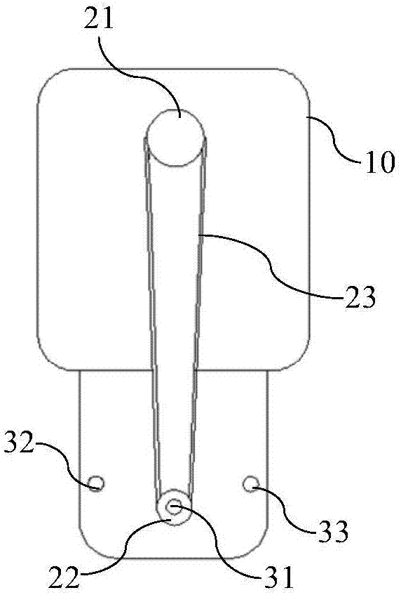
[0027] figure 1 It is a schematic diagram of the front structure of the internal structure of the embodiment of the present invention. figure 2 for figure 1 The side structural cross-sectional view of the internal structure of the embodiment. image 3 for figure 1 A schematic diagram of the internal structure of the lifting arm of the embodiment. As shown in the figure, the reaction tank for wafer etching in this embodiment in...


PUM


Abstract

The invention belongs to the technical field of semiconductors, and particularly relates to a reaction tank for wafer etching. The reaction tank for wafer etching provided by the invention comprises atank body, wherein a lifting arm, a transmission unit and a guiding unit are arranged in the tank body, the interior of the lifting arm is a hollow structure, the transmission unit is arranged in thelifting arm, an input end of the transmission unit is connected with a power source, an output end of the transmission unit is connected with one end of the guiding unit, the other end of the guidingunit passes through the lifting arm and can generate rotation with the lifting arm, and the other end of the guiding unit passing through the lifting arm is used for supporting a wafer and driving the wafer to rotate. By adoption of the reaction tank for wafer etching, the wafer can be rotated in an etching process to effectively and uniformly etch the surface of the wafer, thereby improving thequality of the surface of the wafer.

Description

technical field [0001] The invention belongs to the technical field of semiconductors, and in particular relates to a reaction tank for wafer etching. Background technique [0002] In the prior art, when etching a wafer in a wet process, the entire wafer needs to be immersed in a wafer etching reaction tank and fixed on a wafer support. Since the acid solution in the acid tank of the immersion cleaning machine is always supplied from the bottom of the reaction tank and overflows from the top of the reaction tank, and during this process, the acid solution has been reacting with the film on the wafer, so the acid The local concentration at the top of the tank will be lower than the concentration at the bottom of the acid tank, which means that the acid etching rate at the bottom of the acid tank is higher than that at the top of the acid tank. When the wafer etching process is short, the etching unevenness of the wafer surface is not obvious, but when the wafer is soaked in ...

Claims


Application Information

Patent Timeline
IPC IPC(8): H01L21/67H01L21/687
CPCH01L21/67086H01L21/6875H01L21/68764H01L21/68785H01L21/68792
Inventor 吴良辉
Owner YANGTZE MEMORY TECH CO LTD
Learn More