Supercharge Your Innovation With Domain-Expert AI Agents!

Anti-winding guide plate locating method and rolling mill

The technology of an anti-winding guide plate and a positioning method, which is applied in the field of steel rolling, can solve the problems of complex adjustment method and structure, difficult to achieve precise and stable control stroke, etc., and achieve the effects of low working cost, easy maintenance and convenient operation.

Active Publication Date: 2018-05-01
WISDRI ENG & RES INC LTD
View PDF5 Cites 0 Cited by
  • Summary
  • Abstract
  • Description
  • Claims
  • Application Information

AI Technical Summary

Problems solved by technology

[0006] The structure of this adjustment method is complex, and the adjustment accuracy is greatly affected by factors such as proximity switch accuracy, displacement sensor zero drift, component size tolerance, equipment installation positioning accuracy, etc., it is difficult to achieve accurate and stable control stroke

Method used


Image

  • Anti-winding guide plate locating method and rolling mill
  • Anti-winding guide plate locating method and rolling mill
  • Anti-winding guide plate locating method and rolling mill

Examples


Embodiment 1

[0034] An embodiment of the present invention provides a positioning method for an anti-winding guide plate, the method comprising:

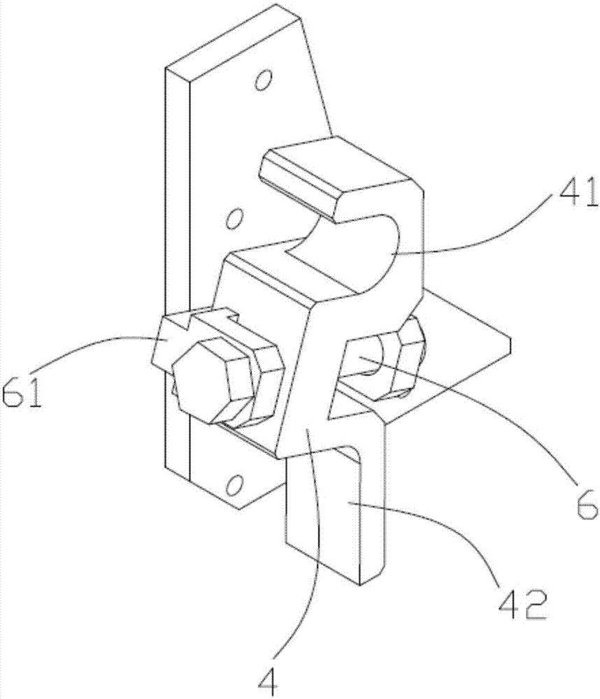
[0035] The first positioning member 4 is arranged on the roll bearing seat 2, and the second positioning member 5 is arranged on the anti-winding guide plate 3. The position of the first positioning member 4 on the bearing seat 2 is adjustable; Before the anti-winding guide plate 3, the position of the first positioning member 4 is marked so that it satisfies: in the process of driving the anti-winding guide plate 3 close to the roll 1, the first positioning member 4 and the second positioning member 5 Cooperate so that the anti-winding guide plate 3 is stopped at the target working position.

[0036] The positioning method of the anti-tangle guide plate provided in this embodiment adopts a simple mechanical positioning method to replace the traditional detection instrument and control system, avoiding the current industry’s conventional relianc...

Embodiment 2

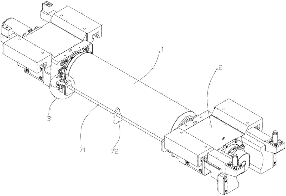
[0056] Such as image 3 and Figure 5 , the embodiment of the present invention relates to a rolling mill, comprising a pair of work rolls 1, at least one of the work rolls 1 is an anti-wrap work roll 1 equipped with an anti-wrap guide plate 3, and the anti-wrap guide plate 3 is connected with a Close to or away from the driving mechanism of the corresponding anti-wrap work roll 1, a first positioning member 4 is provided on the bearing seat 2 of the anti-wrap work roll 1, and a second positioning member 4 is provided on the anti-wrap guide plate 3. Component 5, the position of the first positioning component 4 on the bearing seat 2 is adjustable; the rolling mill is also equipped with a calibration device, which is used to calibrate the position of the first positioning component 4, so that the first positioning The member 4 satisfies: in the process of driving the anti-winding guide plate 3 close to the corresponding anti-winding work roll 1, the first positioning member 4 ...


PUM


Abstract

The invention relates to an anti-winding guide plate locating method and a rolling mill designed based on the locating method. The locating method comprises the steps that first locating components are arranged on roller bearing pedestals, second locating components are arranged on an anti-winding guide plate, and the positions of the first locating components on the bearing pedestals can be adjusted; and before the anti-winding guide plate needs to be located, the positions of the first locating components are calibrated, and the first locating components can meet the conditions that in the process of driving the anti-winding guide plate to get close to a roller, the first locating components and the second locating components cooperate, and therefore the anti-winding guide plate is blocked at the target working position. According to the above locating method, the simple mechanical locating method is adopted for replacing traditional detection instruments and control systems, and theproblems that at present, in the industry, when the anti-winding guide plate is located by conventionally depending on a displacement sensor and a proximity switch, failures are prone to happening under the severe working environment, consequently, precision is lost, and repair and maintenance are complex are avoided; and position calibration of the first locating components can be completed in the roller offline coping procedure, and the work efficiency of online equipment and production continuity are completely not influenced.

Description

technical field [0001] The invention belongs to the technical field of steel rolling, and in particular relates to a positioning method for an anti-winding guide plate and a rolling mill. Background technique [0002] In the cold rolling mill, in order to prevent the strip from being wound around the roll and seal the strip channel when the strip is broken, a specific guide plate needs to be designed to be close to the roll body or even directly pressed against the roll during rolling. body, when the roll is replaced, the guide plate needs to be kept away from the roll; the guide plate is also called the anti-winding guide plate. [0003] Since the roll diameter is constantly changing with the grinding process during the use of the roll, the technological requirement stroke of the anti-wrapping guide plate also changes accordingly. In order to achieve this goal, a lot of work is required in terms of mechanical equipment and electrical control. [0004] In order to achieve ...

Claims


Application Information

Patent Timeline
IPC IPC(8): B21B39/16
CPCB21B39/16
Inventor 杨威王毅祝翠荣
Owner WISDRI ENG & RES INC LTD
Features
  • R&D
  • Intellectual Property
  • Life Sciences
  • Materials
  • Tech Scout
  • Unparalleled Data Quality
  • Higher Quality Content
  • 60% Fewer Hallucinations
Learn More