Injection molding machine

A technology of injection molding machine and constant temperature box, which is applied in the field of injection molding machine equipment, can solve problems such as heat loss, failure to work normally, and increase production costs, and achieve the effects of preventing pipelines from being blocked, low manufacturing costs, and protecting molds

Pending Publication Date: 2018-05-01
浙江元盛塑业股份有限公司
View PDF5 Cites 0 Cited by
  • Summary
  • Abstract
  • Description
  • Claims
  • Application Information

AI Technical Summary

Problems solved by technology

Ordinary nozzles mostly have a one-stage structure and the nozzle itself does not have a heating function, but the heat will always be lost during the process of the raw material flow into the mold
Therefore, after the product is formed, it is easy to produce defects such as cold material marks and white spots.
Moreover, the raw materials in the current plastic production are usually a mixture of several plastic particles, but the melting points of various plastic particles are different, and it is easy to block the flow channel of the nozzle during the continuous temperature change process, resulting in failure to work normally.
The trouble is, when a clog needs to be repaired, the entire nozzle needs to be wrenched off the injection molding machine, which is time consuming, laborious and inefficient
And maintenance must be stopped, which greatly increases production costs
[0006] In addition, in the current injection molding products, some special products require multiple materials, and the existing injection molding machines need to be replaced to inject multiple materials into the same mold, which is very inconvenient

Method used


Image

  • Injection molding machine
  • Injection molding machine
  • Injection molding machine

Examples


Embodiment Construction

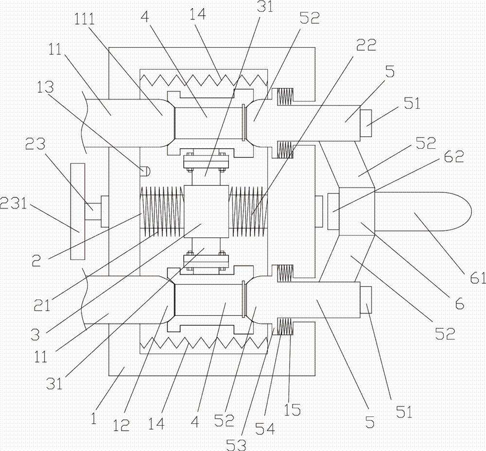
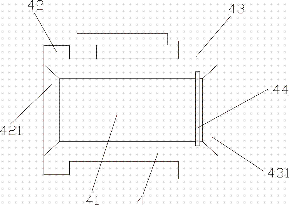
[0018] Below in conjunction with accompanying drawing and specific embodiment the present invention will be described in further detail: Figure 1 to Figure 2 As shown, an injection molding machine includes a constant temperature box 1, a rotating shaft 2 is arranged in the middle of the constant temperature box 1, and several feed pipes are uniformly distributed around the rotary shaft 2 on the side wall of the constant temperature box 1. 11. The feed pipe 11 is connected to different material boxes, and the end of the feed pipe 11 is provided with a semi-spherical discharge end 111; the other side wall of the thermostat 1 corresponds to the feed pipe 11 An equal number of communication holes are provided, and a discharge pipe 5 is arranged in the communication hole, and the discharge pipe 5 is provided with a semi-spherical feeding end 52; the rotary shaft 2 is provided with a connecting part 3, and the A plurality of connection terminals 31 are evenly arranged on the connec...


PUM


Abstract

The invention discloses an injection molding machine, which comprises a constant-temperature box, wherein the constant-temperature box is provided with a rotating shaft, and a side wall of the constant-temperature box is provided with a plurality of feed pipes; the other side wall of the constant-temperature box is provided with a communicating hole, and a discharging pipe is arranged in the communicating hole; the rotating shaft is provided with a connecting part which is provided with a connecting terminal; the connecting terminal is connected with a filtering piece which comprises a filtercartridge; two ends of the filter cartridge are provided with a feeding baffle ring and a discharging baffle ring respectively, and a screen is arranged in the discharging baffle ring; and a communicating pipe is arranged on the side wall of the discharging pipe, and is converged towards the rotating center of the rotating shaft to form a collecting part, and a shoot needle is arranged at the front end of the collecting part. The injection molding machine provided by the invention has a simple structure and a low manufacturing cost, can isolate impurities in the injection molding machine, andcan inject different materials into one mold.

Description

technical field [0001] The invention belongs to the field of injection molding machine equipment, in particular to an injection molding machine. Background technique [0002] Injection molding machine is also known as injection molding machine or injection machine. It is the main molding equipment for making thermoplastics or thermosetting plastics into various shapes of plastic products using plastic molding molds. Divided into vertical, horizontal, all-electric. The injection molding machine heats the plastic, applies high pressure to the molten plastic, and makes it shoot out to fill the mold cavity. [0003] The working principle of the injection molding machine is similar to the syringe used for injection. It uses the thrust of the screw (or plunger) to inject the plastic that has been plasticized into the molten state (that is, the viscous flow state) into the closed cavity. The process of obtaining products after curing and setting. [0004] Injection molding is a...

Claims


Application Information

Patent Timeline
IPC IPC(8): B29C45/17B29C45/74B29C45/20B29B13/10
CPCB29B13/10B29C45/17B29C45/20B29C45/74
Inventor 王文林周岳军沈表
Owner 浙江元盛塑业股份有限公司
Why Eureka
Try Eureka