Boosted engine system of a motor vehicle

A technology of engine and supercharged air, applied in the direction of machines/engines, engine components, combustion engines, etc., can solve problems such as increased fuel consumption, large loss of power generation circuits, and inability to handle electrical needs

Active Publication Date: 2018-05-01
FORD GLOBAL TECH LLC
View PDF39 Cites 1 Cited by
  • Summary
  • Abstract
  • Description
  • Claims
  • Application Information

AI Technical Summary

Problems solved by technology

[0008] Although this approach solves the above-mentioned "turbo lag" problem, it also introduces additional problems: the continuous use of this electric compressor causes a lot of losses to the power generation circuit of the motor vehicle, thereby increasing fuel consumption, and in some Situations requiring additional electrical storage capacity to cope with the operation of an electric compressor at very low engine speeds where the output from the motor vehicle's power generation system cannot handle all of its electrical demands
However, this arrangement is very complex in a configuration requiring many valves and also requires the use of an electric motor capable of withstanding the very high temperatures associated with the turbine section of the second turbocharger

Method used


Image

  • Boosted engine system of a motor vehicle
  • Boosted engine system of a motor vehicle
  • Boosted engine system of a motor vehicle

Examples


Embodiment Construction

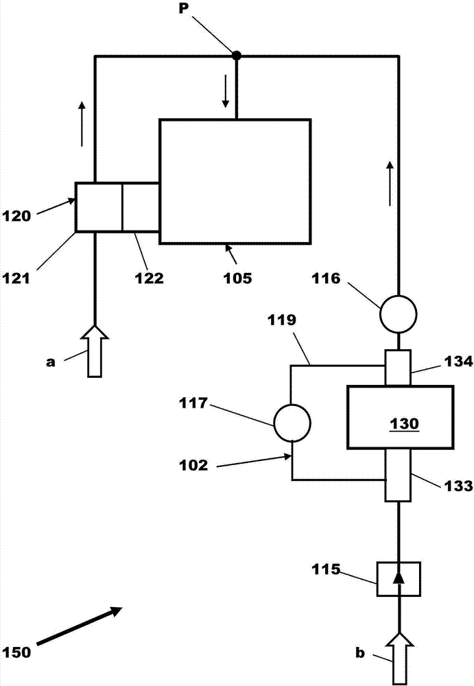
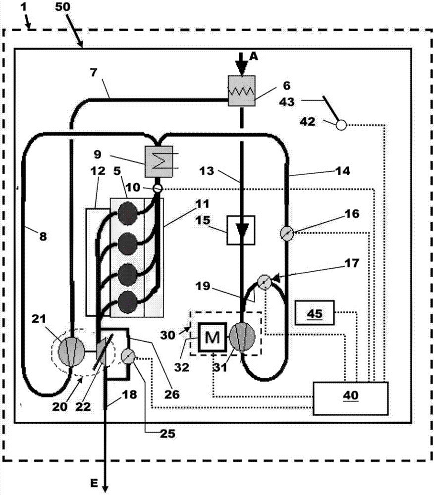
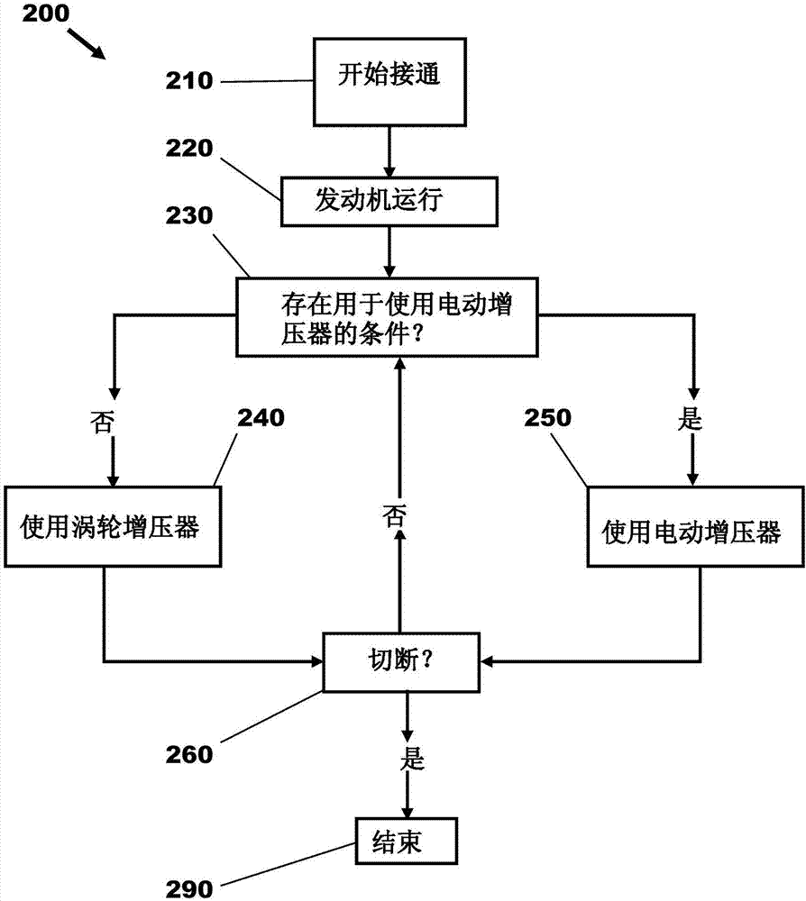
[0017] The following description is concerned with operating an electric compressor arranged in parallel with a turbocharger compressor (such as figure 1 and figure 2 A system and method for providing a desired boost pressure to an engine to deliver an operator demanded torque. another example figure 1 and figure 2 As shown in , the electric compressor may include a recirculation circuit and one or more valves for selectively fluidly coupling the electric compressor with an intake manifold of the engine. In addition to the boost that can be supplied by the turbocharger compressor, when increased boost is required to deliver the current operator demanded torque, the electric compressor can be operated to provide increased boost pressure, such as Figure 3a method is shown. However, the boost pressure output by the electrically operated compressor may first build up within the recirculation loop to a level equal to or greater than the boost pressure provided to the engine ...


PUM


Abstract

The invention relates to a boosted engine system of a motor vehicle. Methods and systems are provided for a boosted engine system having an engine arranged to receive boosted air from a variable geometry turbocharger and an electrically powered compressor arranged in parallel with the turbocharger. During temporary high torque demands above a predefined level, the electrically powered compressor may be used to supplement the flow of boosted air from the turbocharger. Additionally, a recirculation circuit around the electrically powered compressor may be provided to build up pressure in the electrically powered compressor before it is connected to the engine so as to minimize fluctuations in engine boost pressure upon start-up of the electrically powered compressor.

Description

[0001] Cross References to Related Applications [0002] This application claims priority to UK Patent Application No. 1617825.3 filed 21 October 2016 and UK Patent Application No. 1707817.1 filed 16 May 2017. The entire contents of the above-cited applications are hereby incorporated by reference in their entirety for all purposes. technical field [0003] The present invention relates to motor vehicles, and in particular to a supercharged engine system of a motor vehicle having an internal combustion engine and a compressor for increasing the pressure of air entering the engine. Background technique [0004] Internal combustion engines of motor vehicles may include turbochargers to increase the pressure of air entering the engine in order to increase combustion efficiency and torque output. A turbocharger may include a turbine disposed in an exhaust passage of an engine and a compressor disposed in an intake passage of the engine, the compressor being driven by rotation o...

Claims


Application Information

Patent Timeline
Patent Type & Authority Applications(China)
IPC IPC(8): F02B37/04F02B37/12F02B37/16F02B37/18F02D41/00F02B39/10
CPCF02B37/04F02B37/12F02B37/16F02B37/18F02D41/0007F02B39/10F02B37/007F02B37/10F02B37/14F04D25/0606F04D27/002F05D2220/40Y02T10/12F02D2009/0201
Inventor M·J·凯德S·约翰森P·特纳
Owner FORD GLOBAL TECH LLC
Why Eureka
Try Eureka