Grate-layer material separating device for sintering machine

A technology of distributing device and laying bottom material, which is applied in the direction of charge, furnace type, furnace, etc., can solve problems such as damage, achieve the effects of prolonging service life, convenient operation, and reducing the number of replacements

Inactive Publication Date: 2018-05-01
CHINA FIRST METALLURGICAL GROUP
View PDF5 Cites 0 Cited by
  • Summary
  • Abstract
  • Description
  • Claims
  • Application Information

AI Technical Summary

Problems solved by technology

During this period of time, the bottom material belt grate of the sintering machine trolley was in a red-hot state and was severely damaged

Method used


Image

  • Grate-layer material separating device for sintering machine
  • Grate-layer material separating device for sintering machine

Examples


Embodiment Construction

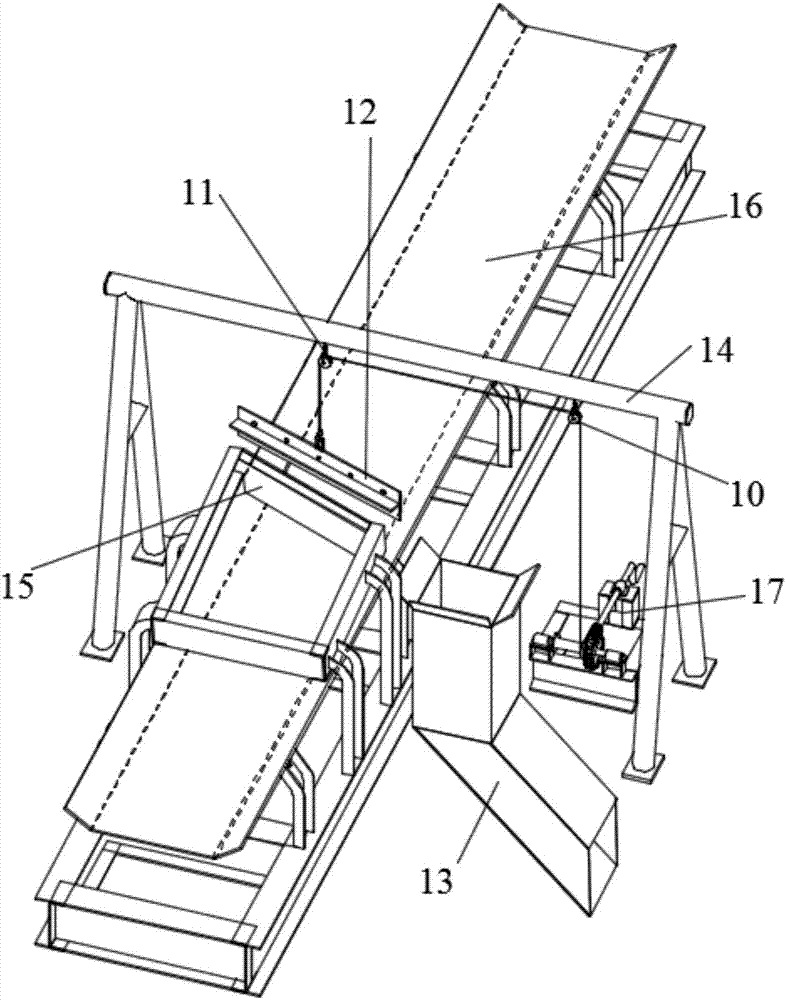
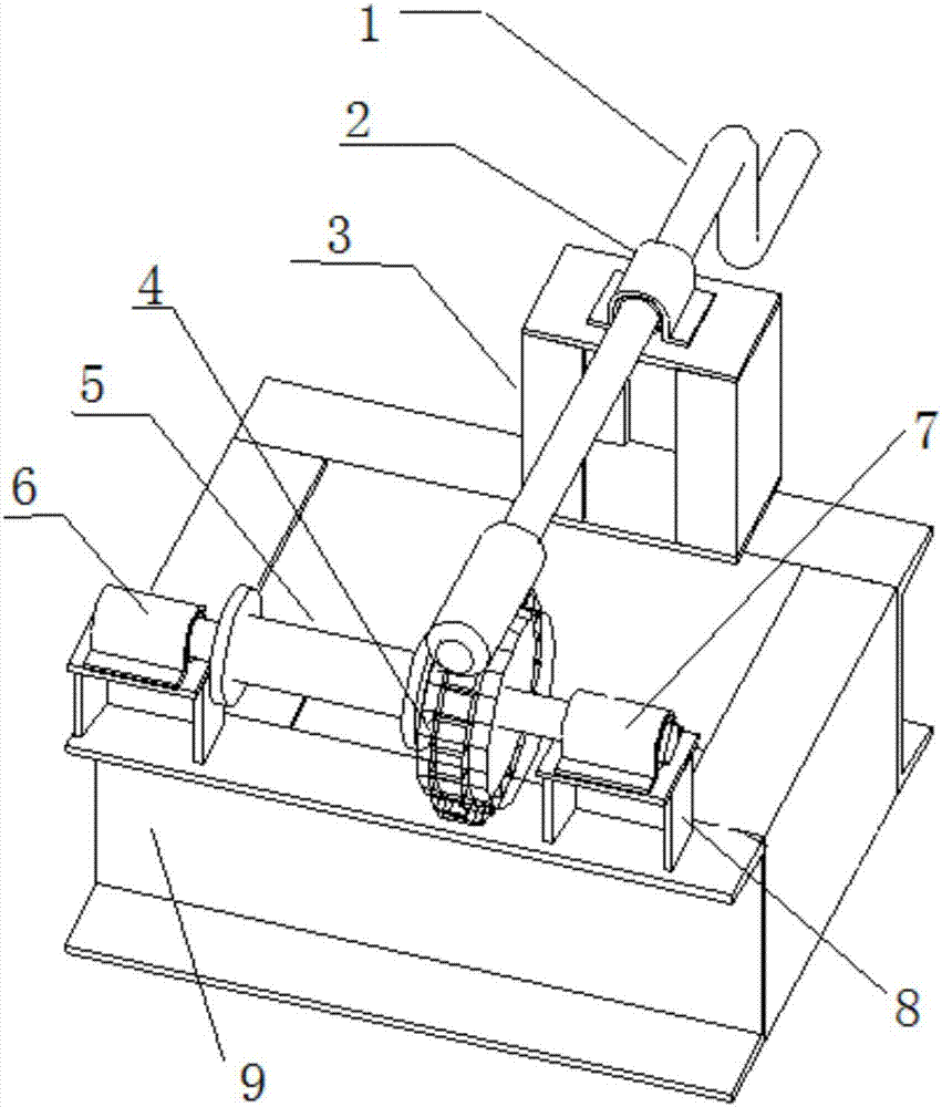
[0023] Below in conjunction with accompanying drawing, the present invention is illustrated, as figure 1 As shown, a bottom material distributing device for a sintering machine shop includes a support plate 15, a material blocking plate 12, a gantry frame 14, a material distribution chute 13 and a lifting device. Directly above the belt 16, the baffle plate 12 is installed on the gantry 14 through the lifting device. When the material baffle plate 12 is lowered by the lifting device, it is just located on the first-stage or second-stage back-laying bottom material belt 16 and on it. The base material is distributed, and the support plate 15 is arranged on the downstream of the material retaining plate 12 through the mounting bracket, and is used to support the material retaining plate 12 to offset the impact of the base material on the material retaining plate 12; the distribution chute 13 The feed inlet is arranged at the material retaining plate 12, and is used to receive th...


PUM


Abstract

The invention discloses a grate-layer material separating device for a sintering machine. The grate-layer material separating device comprises a supporting plate, a retaining plate, a portal frame, aseparating chute and a lifting device; the portal frame is arranged over a first-stage or second-stage grate-layer material returning belt; the retaining plate is installed on the portal frame throughthe lifting device; after being lifted down by the lifting device, the retaining plate is just positioned on the first-stage or second-stage grate-layer material returning belt and is used for separating grate-layer materials on the first-stage or second-stage grate-layer material returning belt; the supporting plate is arranged at the downstream side of the retaining plate through a mounting bracket and is used for supporting the retaining plate; a feeding opening of the separating chute is formed at the retaining plate and is used for receiving the grate-layer materials separated by the retaining plate; and a discharging opening of the separating chute faces to a grate-layer material supply belt of a trolley of a second-stage or first-stage sintering machine. The grate-layer material separating device disclosed by the invention greatly shortens the dry-burning time when the first-stage or second-stage sintering machine starts to work after being overhauled and greatly improves the sintering efficiency and greatly reduces the ore return ratio, and meanwhile the amount of replaced grate bars in every overhauling time is about 800 and is reduced by 90%.

Description

technical field [0001] The invention belongs to the field of sintering machine equipment, and relates to a sintering machine auxiliary equipment, in particular to a sintering machine bed material distributing device. Background technique [0002] The bottom material of the sintering machine is the finished sintered ore with small particles. After passing through the cold sieve, it passes through the bottom material belt for returning to the sintering machine and is laid on the bottom material belt of the sintering machine trolley. In order to prevent the high-temperature exhaust gas from burning the grate and improve the sintering efficiency and sintering quality, while the bottom material is laid on the bottom material belt of the sintering machine trolley to protect the mixed material on the sintering machine from being sucked away by the fan of the sintering machine, increase the output of the sintering machine, and reduce the return rate. The 360m2*2 sintering machine in...

Claims


Application Information

Patent Timeline
Patent Type & Authority Applications(China)
IPC IPC(8): F27B21/08F27D3/00
CPCF27B21/00F27D3/0084F27D2003/0065F27M2003/04
Inventor 岳峰冉江龙王小飞赵家勇李奇张阳
Owner CHINA FIRST METALLURGICAL GROUP
Why Eureka
Try Eureka