Mesh tape-free silicon cell slice sintering furnace

A technology for silicon cells and sintering furnaces, which is applied in the direction of furnaces, circuits, furnace types, etc., and can solve problems such as unsatisfactory sintering process, energy waste, and elevated working environment temperature

Active Publication Date: 2011-05-18
EGING PHOTOVOLTAIC TECHNOLOGY CO LTD
View PDF5 Cites 3 Cited by
  • Summary
  • Abstract
  • Description
  • Claims
  • Application Information

AI Technical Summary

Problems solved by technology

If it is reduced, the furnace temperature zone of the mesh-belt tunnel sintering furnace is not clear, which cannot meet the requirements of the sintering process
In addition, the high temperature resistant mesh belt needs to circulate around the inside and outside of the furnace during operation, and the mesh belt part is accompanied by the heating and cooling process of the silicon wafer. T

Method used


Image

  • Mesh tape-free silicon cell slice sintering furnace
  • Mesh tape-free silicon cell slice sintering furnace
  • Mesh tape-free silicon cell slice sintering furnace

Examples


specific Embodiment approach

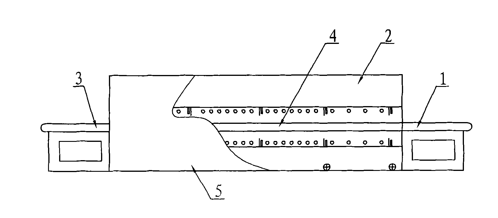
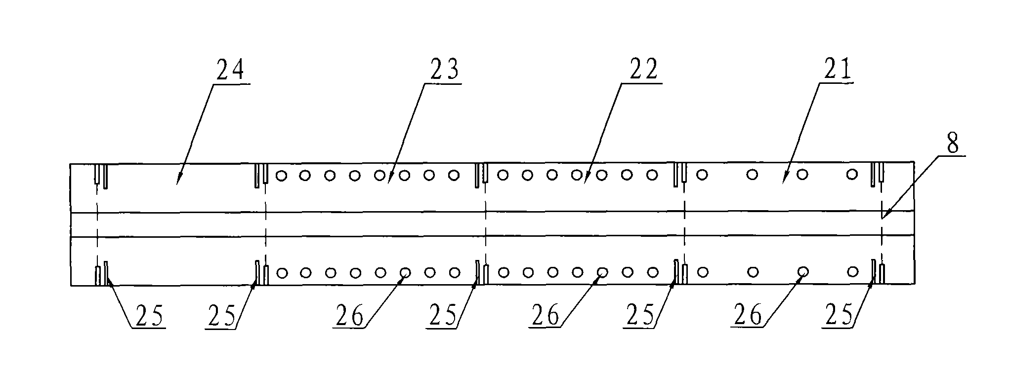
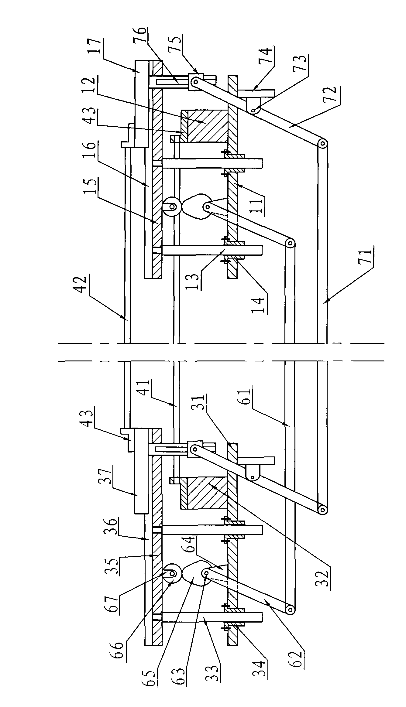
[0031] The non-mesh belt silicon cell sintering furnace is composed of a feeding platform 1, a tunnel type sintering box 2, a discharging platform 3, a silicon wafer conveying device 4 and a furnace frame 5, as figure 1 Shown; Among them, along the longitudinal direction of the tunnel type sintering box 2, there are four regions of preheating debinding area 21, heating area 22, sintering area 23 and cooling area 24, in the preheating debinding area 21, heating area 22, Between the sintering zone 23 and the cooling zone 24, a heat shield 25 and an air-flow insulation door 8 are provided, and a thermal radiation heating lamp tube 26, a heat shield 25 is arranged perpendicular to the direction of the tunnel, and the air-flow insulation door 8 is arranged on one side of the insulation board 25, such as figure 2As shown; the feed table 1 includes a fixed base plate 11, a fixed frame 12, a guide rod 13, a guide sleeve 14, a movable plate 15, a slide rail 16 and a sliding plate 17, ...


PUM


Abstract

The invention provides a mesh tape-free silicon cell slice sintering furnace which comprises a material charging table, a tunnel type sintering box, a material discharging table and a silicon slice transporting device, wherein a preheating glue discharging region, a temperature rising region, a sintering region and a temperature reducing region are sequentially arranged along the lengthways direction of the tunnel type sintering box; a plurality of heat isolating plates and a plurality of air flow heat isolating doors are evenly arranged among a plurality of temperature regions; the preheating glue discharging region, the temperature rising region and the sintering region are internally provided with a plurality of heating lamp tubes; a reciprocating lift mechanism is arranged between a fixed base plate and a movable base plate; a reciprocating translation mechanism is arranged between the fixed base plate and a sliding plate; and the sliding plate sequentially can upwards lift, forwards move, downwards move and backwards move relative to the fixed plate. The silicon slice transporting device comprises a fixed support bracket and a movable support bracket. The heat isolating plates and the air flow heat isolating doors are arranged among the regions, so that the temperature regions can be effectively separated, and the temperature in each temperature region is more close to the requirement of a sintering technology; and a tunnel sintering region is isolated from the atmosphere, so that the sintering efficiency is improved, and the heat dissipation of the sintering furnace is reduced; and therefore, the length of the whole sintering furnace body is shortened.

Description

Technical field: [0001] The invention relates to a production equipment of a photovoltaic cell, in particular to a silicon cell sheet sintering furnace. Background technique: [0002] In the entire production process of solar cells, the three processes of diffusion, coating and sintering are the most important, among which sintering is a crucial step to make the crystalline silicon substrate truly have the photoelectric conversion function. Therefore, the performance of the sintering equipment directly affects the quality of the cell. [0003] At present, solar cell manufacturers at home and abroad generally use mesh-belt tunnel sintering furnaces produced by European and American companies. In the longitudinal direction of the sintering furnace, there are preheating and debinding areas, heating areas, sintering areas and cooling areas in sequence. Heating lamps with different densities are arranged to control the temperature of each area. The silicon wafers of the printed ...

Claims


Application Information

Patent Timeline
IPC IPC(8): F27B9/02F27B9/06F27B9/26F27B9/30H01L31/18
CPCY02P70/50
Inventor 孙铁囤荀建华刘志刚高玉山潘盛姚伟忠陈琼
Owner EGING PHOTOVOLTAIC TECHNOLOGY CO LTD
Why Eureka
Try Eureka