Novel high-temperature sintering furnace

A new type of high-temperature sintering technology, used in furnaces, furnace linings, electric furnace heating, etc., can solve the problems of long time consumption of silicon molybdenum rods, high cost of silicon molybdenum rods, and large amount of work to replace silicon molybdenum rods, so as to improve sintering efficiency and reduce The effect of working strength and easy replacement

Pending Publication Date: 2019-11-08
SUZHOU HUIKE EQUIP CO LTD
View PDF3 Cites 6 Cited by
  • Summary
  • Abstract
  • Description
  • Claims
  • Application Information

AI Technical Summary

Problems solved by technology

Although this structural arrangement can meet the requirements of use, when the silicon-molybdenum rods need to be replaced after a period of use such as one to two years, the silicon-molybdenum rods can only be taken out by removing the aforementioned furnace roof bricks. When the silicon-molybdenum rods are returned, the furnace roof bricks need to be rebuilt. Therefore, not only the engineering volume of replacing the silicon-molybdenum rods is large, but the cost of replacing the silicon-molybdenum rods is high. Therefore, there is a risk of affecting the overall structure of the furnace body, and because the replacement of silicon-molybdenum rods takes a long time and is treated and handled as a project, the sintering furnace is out of service for a long time, which affects electronic components and / or electronic powder materials. The sintering efficiency is high, and because the roof brick needs to be disassembled every time the silicon-molybdenum rod is replaced, it is difficult to guarantee the initial sealing effect, and because the silicon-molybdenum rod will be in the position of the molybdenum rod relief hole of the furnace roof brick at high temperature and The roof bricks bulge into a structure that tends to be integrated, which makes it difficult to remove the roof bricks, because it is necessary to dismantle the multiple roof furnaces that are bulged by silicon-molybdenum rods, so the operator's work intensity is high

Method used


Image

  • Novel high-temperature sintering furnace
  • Novel high-temperature sintering furnace

Examples


Embodiment Construction

[0022] In order to understand the technical essence and beneficial effects of the present invention more clearly, the applicant will describe in detail the following examples, but the descriptions of the examples are not intended to limit the solutions of the present invention. Equivalent transformations that are only formal but not substantive should be regarded as the scope of the technical solution of the present invention.

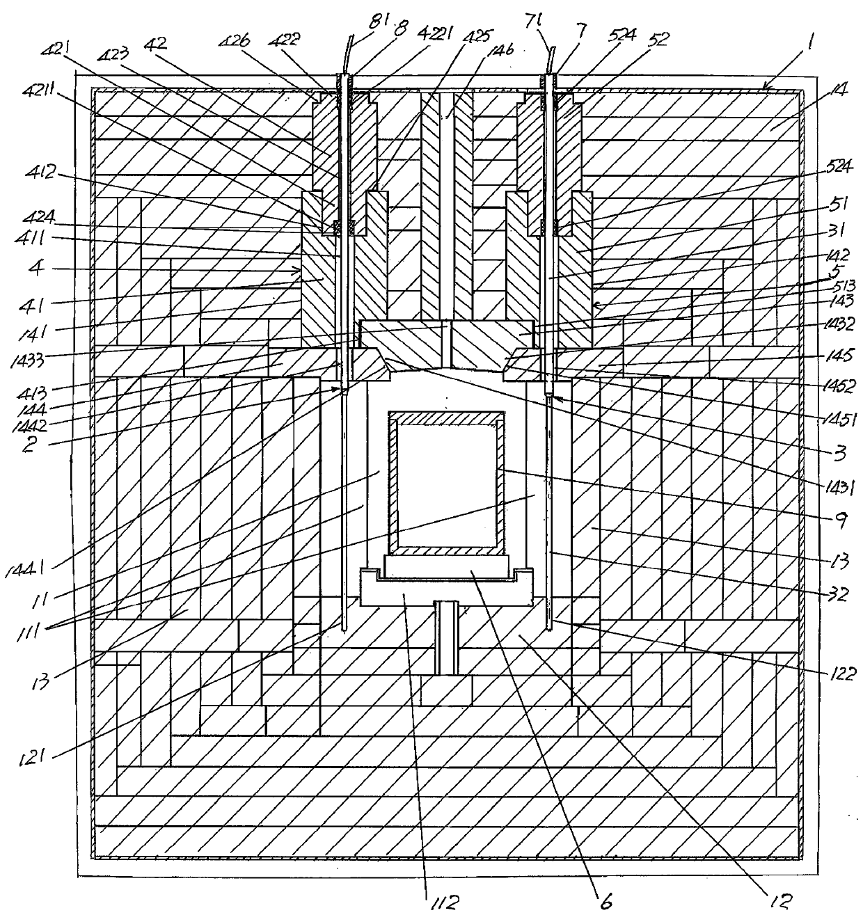
[0023] In the following descriptions, all concepts related to directionality or orientation of up, down, left, right, front and back are based on figure 1 The current position is a reference, so it cannot be understood as a special limitation on the technical solution provided by the present invention.

[0024] See figure 1 , shows a furnace body 1 that belongs to the category of tunnel kiln and has a length of more than ten meters or even tens of meters or even longer. A furnace 11, the furnace 11 is composed of a furnace bottom brick 12 built along...


PUM


Abstract

The invention relates to a novel high-temperature sintering furnace, and belongs to the technical field of kiln facilities. The novel high-temperature sintering furnace comprises a furnace body, wherein a hearth is arranged in the center of the furnace body; a silicon molybdenum rod left heating element is distributed at the position corresponding to the left side of the hearth from the front endof the hearth to the back end; and a silicon molybdenum rod right heating element is distributed at the position corresponding to the right side of the hearth from the front end of the hearth to the back end. The novel high-temperature sintering furnace is characterized in that a left brick filling mechanism holding chamber is formed at the position, corresponding to the silicon molybdenum rod left heating element, on furnace top bricks; a right brick filling mechanism holding chamber is formed at the position, corresponding to the silicon molybdenum rod right heating element, on furnace top bricks; a left brick filling mechanism is arranged in the left brick filling mechanism holding chamber; a right brick filling mechanism is arranged in the right brick filling mechanism holding chamber;the upper end of the silicon molybdenum rod left heating element is matched with the left brick filling mechanism via insertion; and the upper end of the silicon molybdenum rod right heating elementis matched with the right brick filling mechanism via insertion. The engineering cost for replacing silicon molybdenum rods is reduced, the sintering efficiency is improved, a sealing effect of the top part of the hearth cannot be influenced, and the convenience in replacement is realized.

Description

technical field [0001] The invention belongs to the technical field of kiln facilities, and in particular relates to a novel high-temperature sintering furnace. Background technique [0002] As known in the industry, no matter it is used for sintering various electronic components, or for sintering various common and special and high-end electronic powder materials, the structure of the furnace body and the heating components and their setting methods are systemic. its very important component. This can be confirmed by the "hearth structure of battery material sintering furnace" recommended by Chinese patent CN105783517A and the "hearth heating device of MIN sintering furnace" provided by CN204934610U. [0003] Furthermore, as known in the industry, the sintering temperature of some electronic materials such as alumina substrates, aluminum nitride substrates, ceramic substrates, etc. is relatively high, and is around 1500-1600 ° C, so if you use traditional heating wires an...

Claims


Application Information

Patent Timeline
IPC IPC(8): F27B17/00F27D1/00F27D1/02F27D1/04F27D1/16F27D11/02F27D3/02
CPCF27B17/00F27D1/0006F27D1/02F27D1/04F27D1/1621F27D3/026F27D11/02
Inventor 陈龙豪吕华博张文俊计晓铭
Owner SUZHOU HUIKE EQUIP CO LTD
Why Eureka
Try Eureka