Ditching, layer laying and backfilling combined telecommunication cable mechanical laying equipment

A communication cable and integrated technology, which is applied in the field of laying communication cables, can solve the problems of high labor intensity, tediousness, cumbersome and complicated process, etc., and achieve the effect of reducing labor intensity and improving work efficiency

Inactive Publication Date: 2018-05-04
黄正秀
View PDF4 Cites 14 Cited by
  • Summary
  • Abstract
  • Description
  • Claims
  • Application Information

AI Technical Summary

Problems solved by technology

[0003] In order to solve the above problems, the present invention provides a mechanized communication cable laying equipment that integrates trenching, laying and backfilling, which can solve the need for workers to dig trenches, artificial grouting, laying and backfilling in the process of existing direct buried cables. The process of pressing the soil is cumbersome and complicated. When digging trenches, personnel need to use tools to dig the trenches. Long-term bending over work will cause back injuries and cause safety hazards. The unevenness of manual trenches will affect the later work. At the same time, it is cumbersome to deal with the soil after manual trenching. When laying layers, it is necessary to manually grout and roll the bottom of the ditch. The manual rolling is not uniform. When grouting the side, it is necessary to grout the cement board outside and then solidify. Transported to the designated location for installation, gaps are likely to appear between the

Method used


Image

  • Ditching, layer laying and backfilling combined telecommunication cable mechanical laying equipment
  • Ditching, layer laying and backfilling combined telecommunication cable mechanical laying equipment
  • Ditching, layer laying and backfilling combined telecommunication cable mechanical laying equipment

Examples


Embodiment Construction

[0038] In order to make the technical means, creative features, goals and effects achieved by the present invention easy to understand, the present invention will be further described below in conjunction with specific illustrations. It should be noted that, in the case of no conflict, the embodiments in the present application and the features in the embodiments can be combined with each other.

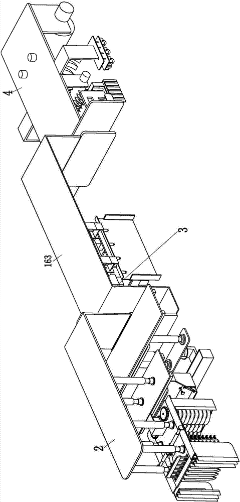
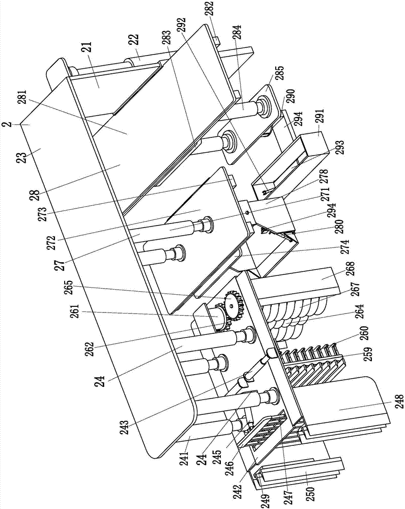
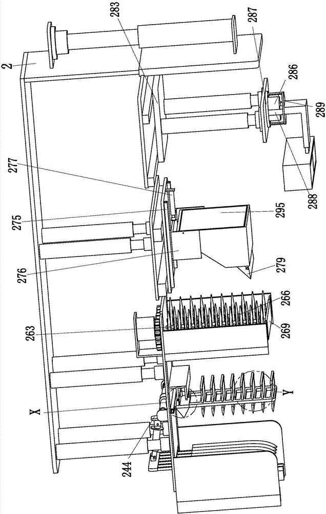
[0039] Such as Figure 1 to Figure 11 As shown, in order to achieve the above object, the present invention adopts the following technical solutions: a kind of mechanized communication cable laying equipment integrating trenching, laying and backfilling, including lifting plate 163, earth digging device 2, grouting device 3 and backfilling device 4. The excavating device 2 plays the role of excavating the soil, the grouting device 3 grouts the excavated soil ditch, and the backfilling device 4 backfills and compacts the excavated soil. The front end of the lifting plate 163 is equipp...


PUM


Abstract

The invention relates to ditching, layer laying and backfilling combined telecommunication cable mechanical laying equipment. The equipment comprises a lifting plate, a soil cutting device, a groutingdevice and a backfilling device, wherein the soil cutting device is mounted at the front end of the lifting plate; the grouting device is mounted at the lower end of the lifting plate; and the backfilling device is mounted at the rear end of the lifting plate. By means of the ditching, layer laying and backfilling combined telecommunication cable mechanical laying equipment, the problems can be solved that in the existing cable direct burying processes, workers need to perform ditching, manual grouting and layer laying, and backfilling and soil rolling; during ditching, the workers need to perform ditching with the help of tools, and the later-stage backfilling effect is affected due to different sizes of soil blocks which are manually cut; and during layer laying, the ditch bottoms needsto be subjected to manual grouting and rolling, cement plates need to be subjected to external grouting and solidification and then delivered to the appointed positions to be mounted during groutingof the side surfaces, cut soil needs to be subjected to manual backfilling and then beating and pressing, and the soil is not compact during manual pressing due to different cut soil blocks, and the functions of automatic ditching, layer laying and backfilling of telecommunication cables can be achieved.

Description

technical field [0001] The invention relates to the technical field of laying communication cables, in particular to a mechanized communication cable laying equipment integrating trenching, laying and backfilling. Background technique [0002] The commonly used types of existing power cables include 10KV overhead insulated cables, parallel set overhead insulated cables, 0.6KV polyvinyl chloride insulated power cables, 1KV polyvinyl chloride insulated power cables, 35KV cross-linked polyvinyl chloride insulated power cables, 450V polyvinyl chloride insulated power cables, Vinyl insulated control cables, 750V polyvinyl chloride insulated control cables and communication cables, etc., the current penetration rate of direct buried cables is very large, among which communication cables are most commonly installed directly buried, due to the large population of cities, land utilization High efficiency, direct buried cables are mostly used in cities, direct buried cables save mater...

Claims


Application Information

Patent Timeline
IPC IPC(8): E02F5/02E02F5/08E02F5/12E02F5/14E02F5/30E02D15/02
CPCE02F5/02E02D15/02E02F5/025E02F5/08E02F5/12E02F5/14E02F5/30
Inventor 黄正秀
Owner 黄正秀
Why Eureka
Try Eureka