Coiled tubing motive sealing device

A dynamic sealing and tubing technology, which is applied in the direction of sealing/packing, drilling pipe, casing, etc., can solve the problems of dynamic sealing devices and methods that have not been disclosed for coiled tubing injection or lifting, so as to improve the effect of hanging and removing, improve effect, effect of reducing waste

Active Publication Date: 2018-05-04
北京中海沃邦能源投资有限公司
View PDF9 Cites 4 Cited by
  • Summary
  • Abstract
  • Description
  • Claims
  • Application Information

AI Technical Summary

Problems solved by technology

Therefore, this technology does not disclose a dynamic sealing device and method for coiled tubing injection or lifting

Method used


Image

  • Coiled tubing motive sealing device
  • Coiled tubing motive sealing device
  • Coiled tubing motive sealing device

Examples


Embodiment 1

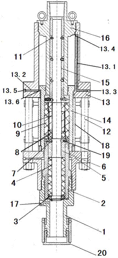
[0029]Embodiment 1, a coiled tubing dynamic sealing device mentioned in the present invention, its technical solution is: including a lower joint 1, a seat seal piston 2, a split ring oil wiper 3, an oil-expandable rubber 4, and a seat seal hydraulic cylinder 5 , rubber pressure ring 6, righting steel ball 7, easy-change rubber pad 8, sealing base sleeve 9, sealing rubber core 10, positioning and righting steel ball 11, connecting bolt 12, rubber replacement cylinder 13, sealing cylinder 14, rubber seat seal The base ring 15, the hollow mandrel 16, the limit support plate 18, the oil wiper 3 of the split ring are installed at the boss of the inner cavity of the lower joint 1, and the upper part of the lower joint 1 is movably connected with the seat seal hydraulic cylinder 5, and the seat seal hydraulic cylinder 5 Install the seat seal piston 2 in the inner cavity of the seat seal piston 2, install the oil-expandable rubber 4 in the inner cavity of the seat seal piston 2, and i...

Embodiment 2

[0045] Embodiment 2, the easy-to-change rubber pad 8 adopted by the present invention is a ring-shaped structure, and an oblique cut is cut in the middle, so that it can be conveniently placed on the working coiled tubing through the oblique cut; in addition, the sealing base sleeve 9 of the present invention is Cylindrical structure, its outer diameter is not greater than the inner diameter of the sealing cylinder 14; the outer diameter of the sealing rubber core 10 is not greater than the inner diameter of the sealing base sleeve 9, so that the sealing rubber core 10 is installed in the inner cavity of the sealing base sleeve 9, and the sealing rubber core Two ends of 10 are installed with one or more sets of easy-change rubber pads 8 respectively; the hardness of the sealing base sleeve 9 is greater than that of the sealing rubber core 10 .

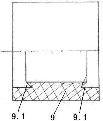
[0046] The middle part of the sealing base sleeve 9 of the present invention is in contact with the sealing rubber core 10, the inner ...

Embodiment 3

[0048] Embodiment 3, with reference to attached Figure 5 The difference between the present invention and Embodiment 1 is that the inlet 13.3 of the first through hole 13.1 does not need to be arranged on the lower outer wall of the rubber replacement cylinder 13, and the outlet does not need to be arranged on the top, and the first through hole does not need to 13.1 is arranged inside the outer wall of the rubber replacement cylinder 13 to reduce production costs; instead, the inlet 13.3 is arranged on the upper part of the outer wall of the rubber replacement cylinder 13, communicates with the outlet 13.4 of the inner wall, injects pressure through the inlet 13.3, and directly enters the air through the outlet 13.4 Cavity, so that the sealing cylinder 14 moves down.


PUM


Abstract

The device provides a coiled tubing motive sealing device, and the technical scheme is that a lower part sealed oil scraping structure and an upper part righting mechanism are connected with a connecting bolt through a limiting support plate; the inner cavity of the support plate is a sealed cylinder; and a sealed basics sleeve, a sealed rubber core and an easily-changed rubber blanket are added on the inner cavity of the sealed cylinder, the sealed rubber core is arranged in the inner cavity of the sealed basics sleeve, thereby opening or closing the limiting support plate, and the sealed basics sleeve, the sealed rubber core or the easily-changed rubber blanket in the inner cavity of the sealed cylinder can be replaced. The coiled tubing motive seal device has the beneficial effects thatmultiple locating righting steel balls are increased to play a role of righting and reducing friction to the coiled tubing; through installing the sealed basics sleeve, the sealed rubber core and theeasily-changed rubber blanket which can be replaced in a split mode in the sealed cylinder, not only can motive sealing of the coiled tubing be realized, but also the replacement of the correspondingsealing elements is facilitated; and oil scraping device is added, the effect of motive sealing is improved, the service life of the coiled tubing is prolonged, and leakage accidents in the wellheadis avoided.

Description

technical field [0001] The invention relates to a device used in the petroleum industry, in particular to a dynamic sealing device for coiled tubing. Background technique [0002] Coiled tubing is a pipe made of low-carbon alloy steel with good flexibility. It is also called flexible tubing. It is wound on the drum and adopts special injection equipment. It can be continuously lowered into the well or pulled out from the oil well. The long tubing without thread connection can solve problems that cannot be solved by conventional operation methods. Coiled tubing can be used in workover, well completion, logging, pipeline gathering and transportation and other fields. The main advantages of coiled tubing are: [0003] 1. Improve the operation efficiency, because the coiled tubing equipment is less, the lifting speed is fast, and the workover time is shortened by more than 2 / 3; [0004] 2. Reduce operating costs, use coiled tubing for drilling and workover operations, the workl...

Claims


Application Information

Patent Timeline
Patent Type & Authority Applications(China)
IPC IPC(8): E21B33/127E21B17/10
CPCE21B17/1078E21B33/127E21B37/02
Inventor 王鲁洋
Owner 北京中海沃邦能源投资有限公司
Why Eureka
Try Eureka